Information injection-pump assembly
ZEXEL
101606-1110
1016061110

Rating:
Cross reference number
ZEXEL
101606-1110
1016061110
Zexel num
Bosch num
Firm num
Name
Calibration Data:
Adjustment conditions
Test oil
1404 Test oil ISO4113 or {SAEJ967d}
1404 Test oil ISO4113 or {SAEJ967d}
Test oil temperature
degC
40
40
45
Nozzle and nozzle holder
105780-8140
Bosch type code
EF8511/9A
Nozzle
105780-0000
Bosch type code
DN12SD12T
Nozzle holder
105780-2080
Bosch type code
EF8511/9
Opening pressure
MPa
17.2
Opening pressure
kgf/cm2
175
Injection pipe
Outer diameter - inner diameter - length (mm) mm 6-2-600
Outer diameter - inner diameter - length (mm) mm 6-2-600
Overflow valve
131424-5520
Overflow valve opening pressure
kPa
255
221
289
Overflow valve opening pressure
kgf/cm2
2.6
2.25
2.95
Tester oil delivery pressure
kPa
157
157
157
Tester oil delivery pressure
kgf/cm2
1.6
1.6
1.6
Direction of rotation (viewed from drive side)
Left L
Left L
Injection timing adjustment
Direction of rotation (viewed from drive side)
Left L
Left L
Injection order
1-5-3-6-
2-4
Pre-stroke
mm
3.6
3.55
3.65
Beginning of injection position
Governor side NO.1
Governor side NO.1
Difference between angles 1
Cal 1-5 deg. 60 59.5 60.5
Cal 1-5 deg. 60 59.5 60.5
Difference between angles 2
Cal 1-3 deg. 120 119.5 120.5
Cal 1-3 deg. 120 119.5 120.5
Difference between angles 3
Cal 1-6 deg. 180 179.5 180.5
Cal 1-6 deg. 180 179.5 180.5
Difference between angles 4
Cyl.1-2 deg. 240 239.5 240.5
Cyl.1-2 deg. 240 239.5 240.5
Difference between angles 5
Cal 1-4 deg. 300 299.5 300.5
Cal 1-4 deg. 300 299.5 300.5
Injection quantity adjustment
Adjusting point
-
Rack position
11.3
Pump speed
r/min
850
850
850
Each cylinder's injection qty
mm3/st.
65.4
63.5
67.3
Basic
*
Fixing the rack
*
Standard for adjustment of the maximum variation between cylinders
*
Injection quantity adjustment_02
Adjusting point
H
Rack position
9.9+-0.5
Pump speed
r/min
275
275
275
Each cylinder's injection qty
mm3/st.
9.2
8.1
10.3
Fixing the rack
*
Standard for adjustment of the maximum variation between cylinders
*
Injection quantity adjustment_03
Adjusting point
A
Rack position
R1(11.3)
Pump speed
r/min
850
850
850
Average injection quantity
mm3/st.
65.4
64.4
66.4
Basic
*
Fixing the lever
*
Injection quantity adjustment_04
Adjusting point
B
Rack position
R1+0.6
Pump speed
r/min
1450
1450
1450
Average injection quantity
mm3/st.
81.2
77.2
85.2
Fixing the lever
*
Injection quantity adjustment_05
Adjusting point
C
Rack position
R1+0.1
Pump speed
r/min
600
600
600
Average injection quantity
mm3/st.
51.5
47.5
55.5
Fixing the lever
*
Injection quantity adjustment_06
Adjusting point
I
Rack position
-
Pump speed
r/min
100
100
100
Average injection quantity
mm3/st.
80
75
85
Fixing the lever
*
Rack limit
*
Timer adjustment
Pump speed
r/min
1250--
Advance angle
deg.
0
0
0
Remarks
Start
Start
Timer adjustment_02
Pump speed
r/min
1200
Advance angle
deg.
0.5
Timer adjustment_03
Pump speed
r/min
1350
Advance angle
deg.
2.4
1.9
2.9
Timer adjustment_04
Pump speed
r/min
1500
Advance angle
deg.
5
4.5
5.5
Remarks
Finish
Finish
Test data Ex:
Governor adjustment
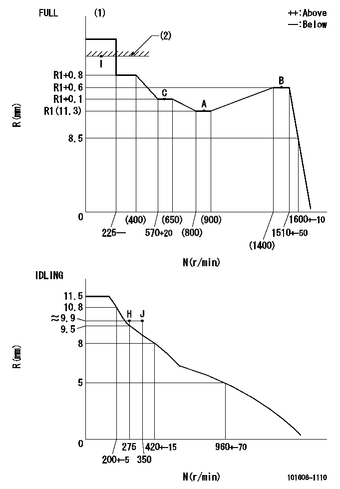
N:Pump speed
R:Rack position (mm)
(1)Torque cam stamping: T1
(2)RACK LIMIT
----------
T1=C14
----------
----------
T1=C14
----------
Speed control lever angle

F:Full speed
I:Idle
(1)Stopper bolt set position 'H'
----------
----------
a=18.5deg+-5deg b=(42deg)+-3deg
----------
----------
a=18.5deg+-5deg b=(42deg)+-3deg
Stop lever angle

N:Engine manufacturer's normal use
S:Stop the pump.
(1)Set the stopper bolt at speed = rated point and rack position = aa (non-injection rack position). Confirm non-injection.
(2)After setting the stopper bolt , confirm non-injection at pump speed bb. Rack position = cc (non-injection rack position).
(3)Rack position = approximately dd
(4)Free (at shipping)
----------
aa=7mm bb=275r/min cc=(8)mm dd=17.4mm
----------
a=38.5deg+-5deg b=(27deg) c=17deg+-5deg
----------
aa=7mm bb=275r/min cc=(8)mm dd=17.4mm
----------
a=38.5deg+-5deg b=(27deg) c=17deg+-5deg
0000001501 MICRO SWITCH
Adjustment of the micro-switch
Adjust the bolt to obtain the following lever position when the micro-switch is ON.
(1)Speed N1
(2)Rack position Ra
----------
N1=400+-5r/min Ra=9.7mm
----------
----------
N1=400+-5r/min Ra=9.7mm
----------
Timing setting

(1)Pump vertical direction
(2)Position of timer's tooth at No 1 cylinder's beginning of injection
(3)B.T.D.C.: aa
(4)-
----------
aa=12deg
----------
a=(1deg)
----------
aa=12deg
----------
a=(1deg)
Information:
Adjustto conform and correspond to specifications.Checkto observe for satisfactory conditions, accuracy, safety or performance.Exchangeto trade a worn or failing component for a remanufactured or rebuilt component.Inspectto examine closely, in critical appraisal, while testing or evaluating components or systems.Inspect/Rebuild or Exchangeto examine closely; then making the decision on repair option (Rebuild or Exchange).Lubricateto apply a lubricant (oil, grease, etc.) as specified for reducing friction, heat and wear between solid surfaces.Rebuildto repair a worn or failing component with new parts, components and/or remanufactured components.Replaceto install something new, remanufactured or rebuilt in place of an existing worn or failing component.Maintenance Intervals
The Maintenance Schedule requires all previous interval maintenance items to be performed first. For instance, if the PM Level 2 maintenance is being performed, then the PM Level 1 and Daily maintenance items must be completed BEFORE performing the PM Level 2 maintenance.Interval Terminology
Engine components can generally be grouped into speed sensitive and load sensitive categories. Therefore, the maintenance interval for each item listed in the Maintenance Schedule is primarily based on the item and its relationship to either engine speed or load. Speed sensitive items such as water pumps, alternators, air compressors, etc., are not primarily affected by the load on your engine during operation. The load on an engine will not significantly accelerate the repair or replacement cycle for speed sensitive items. Therefore, the maintenance intervals established for speed sensitive items are based on time and service hour intervals. Load sensitive items are affected by the load on your engine during operation. Generally speaking, the lower the load, the longer the engine life and conversely, the higher the load, the shorter the engine life. A heavy load on an engine will accelerate the repair or replacement cycle for load sensitive items.Load sensitive items are normally internal engine components. The amount of fuel consumed is directly related to the load on your engine. The amount of fuel consumed is a better indicator of when to perform maintenance than time, however Caterpillar recognizes that fuel consumption is difficult to document in some applications. An estimated fuel consumption figure can be used to determine some intervals.Maintenance Options
Rebuild with New Parts - Genuine Caterpillar parts are constantly tested and modified to incorporate the latest design advancements. Caterpillar may rebuild or provide the parts needed for overhauling your engine. Your benefit; long lasting replacement parts at competitive prices. New Components - Replace worn or failing components with new components. Repair Kits - These useful kits may be obtained from Caterpillar. These kits include all the necessary parts and instructions to repair the components in the owner's maintenance shop or at a Caterpillar servicing facility. Repair kits simplify parts ordering, help speed repairs and reduce parts cost. Exchange - This cost-cutting service permits you to exchange worn engine components for quality Caterpillar Remanufactured components on an over-the-counter basis. When you need them, these parts are ready for a substantial savings in both time and money. Caterpillar Factory Remanufactured Components - The latest remanufacturing techniques and