Information injection-pump assembly
ZEXEL
101606-1090
1016061090
Rating:
Cross reference number
ZEXEL
101606-1090
1016061090
Zexel num
Bosch num
Firm num
Name
Calibration Data:
Adjustment conditions
Test oil
1404 Test oil ISO4113 or {SAEJ967d}
1404 Test oil ISO4113 or {SAEJ967d}
Test oil temperature
degC
40
40
45
Nozzle and nozzle holder
105780-8140
Bosch type code
EF8511/9A
Nozzle
105780-0000
Bosch type code
DN12SD12T
Nozzle holder
105780-2080
Bosch type code
EF8511/9
Opening pressure
MPa
17.2
Opening pressure
kgf/cm2
175
Injection pipe
Outer diameter - inner diameter - length (mm) mm 6-2-600
Outer diameter - inner diameter - length (mm) mm 6-2-600
Overflow valve
131424-5520
Overflow valve opening pressure
kPa
255
221
289
Overflow valve opening pressure
kgf/cm2
2.6
2.25
2.95
Tester oil delivery pressure
kPa
157
157
157
Tester oil delivery pressure
kgf/cm2
1.6
1.6
1.6
Direction of rotation (viewed from drive side)
Left L
Left L
Injection timing adjustment
Direction of rotation (viewed from drive side)
Left L
Left L
Injection order
1-5-3-6-
2-4
Pre-stroke
mm
3.3
3.25
3.35
Beginning of injection position
Governor side NO.1
Governor side NO.1
Difference between angles 1
Cal 1-5 deg. 60 59.5 60.5
Cal 1-5 deg. 60 59.5 60.5
Difference between angles 2
Cal 1-3 deg. 120 119.5 120.5
Cal 1-3 deg. 120 119.5 120.5
Difference between angles 3
Cal 1-6 deg. 180 179.5 180.5
Cal 1-6 deg. 180 179.5 180.5
Difference between angles 4
Cyl.1-2 deg. 240 239.5 240.5
Cyl.1-2 deg. 240 239.5 240.5
Difference between angles 5
Cal 1-4 deg. 300 299.5 300.5
Cal 1-4 deg. 300 299.5 300.5
Injection quantity adjustment
Adjusting point
A
Rack position
9.2
Pump speed
r/min
1400
1400
1400
Average injection quantity
mm3/st.
73.8
72.8
74.8
Max. variation between cylinders
%
0
-2.5
2.5
Basic
*
Fixing the lever
*
Injection quantity adjustment_02
Adjusting point
C
Rack position
8+-0.5
Pump speed
r/min
350
350
350
Average injection quantity
mm3/st.
12.6
11.1
14.1
Max. variation between cylinders
%
0
-15
15
Fixing the rack
*
Timer adjustment
Pump speed
r/min
850--
Advance angle
deg.
0
0
0
Remarks
Start
Start
Timer adjustment_02
Pump speed
r/min
800
Advance angle
deg.
0.5
Timer adjustment_03
Pump speed
r/min
1400
Advance angle
deg.
5
4.5
5.5
Remarks
Finish
Finish
Test data Ex:
Governor adjustment
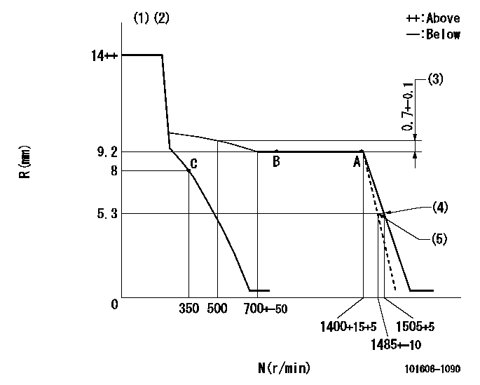
N:Pump speed
R:Rack position (mm)
(1)Target notch: K
(2)Supplied with torque spring not set.
(3)Rack difference between N = N1 and N = N2
(4)Set idle sub-spring
(5)Main spring setting
----------
K=11 N1=1400r/min N2=500r/min
----------
----------
K=11 N1=1400r/min N2=500r/min
----------
Speed control lever angle

F:Full speed
I:Idle
(1)Stopper bolt setting
----------
----------
a=27deg+-5deg b=17deg+-5deg
----------
----------
a=27deg+-5deg b=17deg+-5deg
Stop lever angle

N:Pump normal
S:Stop the pump.
----------
----------
a=26deg+-5deg b=53deg+-5deg
----------
----------
a=26deg+-5deg b=53deg+-5deg
Timing setting

(1)Pump vertical direction
(2)Position of timer's tooth at No 1 cylinder's beginning of injection
(3)B.T.D.C.: aa
(4)-
----------
aa=18deg
----------
a=(2deg)
----------
aa=18deg
----------
a=(2deg)
Information:
Air Inlet Heater
To aid cold weather starting and reduce white smoke at start-up, the Caterpillar 3114 and 3116 diesel engines are equipped with an electric air heater grid located at the air inlet elbow. The heater control module senses engine oil pressure, engine coolant temperature, and time. Under the proper conditions, the control module activates a switch (solenoid), which turns the heater on and off. The heater grid, solenoid, control module and sensors are part of the engine arrangement.Operation
The air inlet heater system is designed to provide heat prior to start-up, during cranking, and after the engine has started. If the coolant temperature is below the preset limit, the control module allows the heater to stay on for pre-heating up to 30 seconds when the ignition is turned to the RUN position. An indicator lamp in the instrument panel is lit when the unit is on.Lamp Test
When the ignition switch is turned to the RUN position, the control module energizes the switch, supplying the heater element with power for two seconds. The indicator lamp in the instrument panel will illuminate at that time. Failure of the lamp to light indicates a system malfunction. If the coolant temperature is below the preset limit, the system should go directly from the lamp test into the pre-heat cycle (lamp will NOT turn off). For more detailed information on the air inlet heater, consult the Systems Operation section of the Truck Engine Service Manual.Refer to the Truck Owner Manual for starting procedures relating to the use of coolant and/or crankcase oil heaters.Priming Fuel System After Filter Change
After changing the fuel filter(s), prime (purge) the fuel system to remove air bubbes from the system. DO NOT remove the plug in the fuel filter base to release air from the fuel system while priming. Periodic removal of the plug will result in increased wear of the threads in the fuel filter base and lead to fuel leakage. 1. Loosen Fuel Filter Air Bleed Vent Cap two full turns. Unlock and operate the priming pump plunger until fuel appears at the cap. Use a cloth or container to catch excess fuel. Twenty five to thirty pump strokes may be required to fill filter.2. Tighten Fuel Filter Air Bleed Cap and continue to operate priming pump until a resistance is felt. Push the plunger in and tighten by hand and promptly continue with next step.
Do not crank the engine continuously for more than 30 seconds. Allow the starter to cool for two minutes before cranking again.
3. Crank the engine promptly after pressurizing fuel system. The engine should start within 15 seconds.4. If the engine will not start, or once started continues to misfire or smoke, further priming is necessary to help purge fuel system of air before air bubbles enter fuel injectors. Allow starting motor two minutes to cool and repeat step #2 and crank again.5. If the engine starts, but runs rough, then continue to run the engine at low idle until fuel flows free