Information injection-pump assembly
ZEXEL
101606-0170
1016060170
ISUZU
8976004570
8976004570
Rating:
Cross reference number
ZEXEL
101606-0170
1016060170
ISUZU
8976004570
8976004570
Zexel num
Bosch num
Firm num
Name
Calibration Data:
Adjustment conditions
Test oil
1404 Test oil ISO4113 or {SAEJ967d}
1404 Test oil ISO4113 or {SAEJ967d}
Test oil temperature
degC
40
40
45
Nozzle and nozzle holder
105780-8260
Bosch type code
9 430 610 133
Nozzle
105780-0120
Bosch type code
1 688 901 990
Nozzle holder
105780-2190
Opening pressure
MPa
18
Opening pressure
kgf/cm2
184
Injection pipe
Outer diameter - inner diameter - length (mm) mm 6-2-600
Outer diameter - inner diameter - length (mm) mm 6-2-600
Overflow valve
131424-8620
Overflow valve opening pressure
kPa
206
172
240
Overflow valve opening pressure
kgf/cm2
2.1
1.75
2.45
Tester oil delivery pressure
kPa
255
255
255
Tester oil delivery pressure
kgf/cm2
2.6
2.6
2.6
Direction of rotation (viewed from drive side)
Left L
Left L
Injection timing adjustment
Direction of rotation (viewed from drive side)
Left L
Left L
Injection order
1-5-3-6-
2-4
Pre-stroke
mm
3.8
3.75
3.85
Rack position
Point A R=A
Point A R=A
Beginning of injection position
Governor side NO.1
Governor side NO.1
Difference between angles 1
Cal 1-5 deg. 60 59.5 60.5
Cal 1-5 deg. 60 59.5 60.5
Difference between angles 2
Cal 1-3 deg. 120 119.5 120.5
Cal 1-3 deg. 120 119.5 120.5
Difference between angles 3
Cal 1-6 deg. 180 179.5 180.5
Cal 1-6 deg. 180 179.5 180.5
Difference between angles 4
Cyl.1-2 deg. 240 239.5 240.5
Cyl.1-2 deg. 240 239.5 240.5
Difference between angles 5
Cal 1-4 deg. 300 299.5 300.5
Cal 1-4 deg. 300 299.5 300.5
Injection quantity adjustment
Adjusting point
-
Rack position
14.1
Pump speed
r/min
850
850
850
Average injection quantity
mm3/st.
128.5
126.9
130.1
Max. variation between cylinders
%
0
-2.5
2.5
Basic
*
Fixing the rack
*
Standard for adjustment of the maximum variation between cylinders
*
Injection quantity adjustment_02
Adjusting point
Z
Rack position
9.5+-0.5
Pump speed
r/min
300
300
300
Average injection quantity
mm3/st.
15.5
14.2
16.8
Max. variation between cylinders
%
0
-14
14
Fixing the rack
*
Standard for adjustment of the maximum variation between cylinders
*
Injection quantity adjustment_03
Adjusting point
A
Rack position
R1(14.1)
Pump speed
r/min
850
850
850
Average injection quantity
mm3/st.
128.5
127.5
129.5
Basic
*
Fixing the lever
*
Injection quantity adjustment_04
Adjusting point
B
Rack position
(R1+1.15
)+0.05-0
.15
Pump speed
r/min
1450
1450
1450
Average injection quantity
mm3/st.
130
126.8
133.2
Fixing the lever
*
Test data Ex:
Governor adjustment
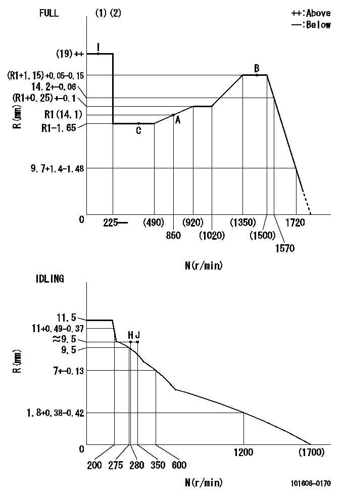
N:Pump speed
R:Rack position (mm)
(1)Torque cam stamping: T1
(2)Tolerance for racks not indicated: +-0.05mm.
----------
T1=N97
----------
----------
T1=N97
----------
Timer adjustment

(1)Adjusting range
(2)Step response time
(N): Speed of the pump
(L): Load
(theta) Advance angle
(Srd1) Step response time 1
(Srd2) Step response time 2
1. Adjusting conditions for the variable timer
(1)Adjust the clearance between the pickup and the protrusion to L.
----------
L=1.5+-0.2mm N2=800r/min C2=(8deg) t1=2--sec. t2=2--sec.
----------
N1=1300++r/min P1=0kPa(0kgf/cm2) P2=392kPa(4kgf/cm2) C1=8+-0.3deg R01=0/4load R02=4/4load
----------
L=1.5+-0.2mm N2=800r/min C2=(8deg) t1=2--sec. t2=2--sec.
----------
N1=1300++r/min P1=0kPa(0kgf/cm2) P2=392kPa(4kgf/cm2) C1=8+-0.3deg R01=0/4load R02=4/4load
Speed control lever angle
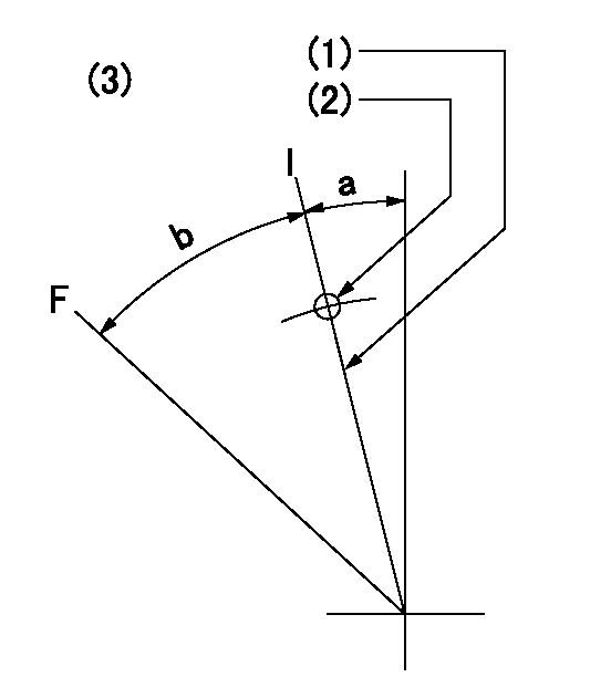
F:Full speed
I:Idle
(1)Stopper bolt set position 'H'
(2)Use the pin at R = aa
(3)Viewed from feed pump side.
----------
aa=33mm
----------
a=12deg+-5deg b=47.5deg+-3deg
----------
aa=33mm
----------
a=12deg+-5deg b=47.5deg+-3deg
Stop lever angle

N:Pump normal
S:Stop the pump.
(1)Use the pin at R = aa
----------
aa=45mm
----------
a=12.5deg+-5deg b=40deg+-5deg
----------
aa=45mm
----------
a=12.5deg+-5deg b=40deg+-5deg
0000001501 RACK SENSOR
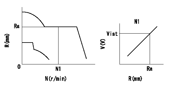
Rack sensor adjustment
1. Flange type rack sensor (rack sensor adjustment -5*20)
(1)These types of rack sensors do not need adjustment. Confirm the performance with the following procedures.
(2)Mount the rack sensor main body to the pump main body.
(3)Fix the pump lever at full.
(4)At supply voltage V1, pump speed N1 and rack position Ra, confirm that the amp's output voltage is Vist.
(5)Move the pump lever two or three times.
(6)Set again to full.
(7)Confirm that the amplifier output voltage is Vist.
(8)Fix the caution plate to the upper part of the rack sensor.
(For those without the caution plate instructions, make sure the nameplate of the rack sensor carries the "Don't hold here" caution.)
(9)Apply red paint to the rack sensor mounting bolts (2 places).
----------
V1=5+-0.01V N1=850r/min Ra=R1(14.1)mm Vist=3.55+-0.28V
----------
----------
V1=5+-0.01V N1=850r/min Ra=R1(14.1)mm Vist=3.55+-0.28V
----------
Timing setting

(1)Pump vertical direction
(2)Positions of coupling's threaded installation holes at No 1 cylinder's beginning of injection
(3)B.T.D.C.: aa
(4)-
----------
aa=6deg
----------
a=(160deg)
----------
aa=6deg
----------
a=(160deg)
Information:
Introduction
The objective of this topic is to assist users in establishing a Preventive Maintenance Program for Standby Generator Sets or as an aid in evaluating their present programs.Standby Generator Sets may not be needed very often, but when they are, it is usually under emergency conditions. Maintenance of these standby units is very important. They must always be in excellent operating condition, ready to work under load at any time.Establishing a Preventive Maintenance Program will provide maximum availability of a standby generator set when needed, longer engine and generator life, and a minimum of expensive repairs.The recommended WEEKLY maintenance checks can be performed by an operator. The checks consist of basic maintenance requirements to ensure the standby generator set will be ready for immediate use should the need arise.All YEARLY and THREE YEAR maintenance should be performed by an authorized mechanic or your Caterpillar dealer. These checks and maintenance requirements will require that the standby generator be run under load conditions, and may require special test equipment.These guidelines are to be used with the information contained in the Operation and Maintenance sections of this manual. The Operation and Maintenance sections of the manual will provide the necessary information on how to perform the checks and routine maintenance.Refer to the Generator and Engine Service Manuals and Recommended Preventive Maintenance Schedules for Standby Generator Sets, SEBU6042 for additional information, or contact your Caterpillar dealer for assistance.Inspection and Maintenance Agreements
Your Caterpillar dealer can establish an Inspection and Preventive Maintenance Program for your generator set to provide maximum reliability, increased engine and generator life, and minimize expensive repairs. Contact your Caterpillar dealer for details.General Recommendations
Safety
The stop-manual-automatic switch on the cranking panel must be set at STOP position when performing maintenance or repair work on a standby generator set. This prevents the unit from starting if a power failure or voltage drop should occur while working on the unit.To prevent personal injury due to accidental starting of the engine, disconnect the batteries or disable the starting system before doing maintenance or repair work.Lock out all switch gear and automatic transfer switches associated with the generator while performing any generator maintenance or repairs. Make sure no shock hazard exists.Failure to comply could result in personal injury or death.
Always make repairs with the engine stopped and the starting system disabled. When servicing the generator, make sure that switch gear and automatic transfer switches will not present a shock hazard. Lock them out on the generator being serviced.Record Keeping
Maintain a log or record keeping system to document all gauge readings, problems, repairs, and maintenance performed on the equipment.Space Heaters
Moisture is a natural enemy of generators and all electrical equipment. Every effort must be made to keep the generator as dry as possible. Space heaters should be operated inside the generator when it is not in use to maintain the integrity of the generator windings.