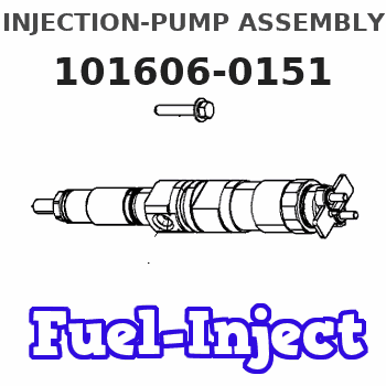
Information injection-pump assembly
BOSCH
9 400 615 407
9400615407
ZEXEL
101606-0151
1016060151
ISUZU
8976004551
8976004551
Rating:
Service parts 101606-0151 INJECTION-PUMP ASSEMBLY:
1.
_
7.
COUPLING PLATE
8.
_
9.
_
11.
Nozzle and Holder
8-94391-291-4
12.
Open Pre:MPa(Kqf/cm2)
16.2{165}/19.6{200}
14.
NOZZLE
Cross reference number
BOSCH
9 400 615 407
9400615407
ZEXEL
101606-0151
1016060151
ISUZU
8976004551
8976004551
Zexel num
Bosch num
Firm num
Name
101606-0151
9 400 615 407
8976004551 ISUZU
INJECTION-PUMP ASSEMBLY
6HL1-S K 14BF INJECTION PUMP ASSY PE6AD PE
6HL1-S K 14BF INJECTION PUMP ASSY PE6AD PE
Calibration Data:
Adjustment conditions
Test oil
1404 Test oil ISO4113 or {SAEJ967d}
1404 Test oil ISO4113 or {SAEJ967d}
Test oil temperature
degC
40
40
45
Nozzle and nozzle holder
105780-8260
Bosch type code
9 430 610 133
Nozzle
105780-0120
Bosch type code
1 688 901 990
Nozzle holder
105780-2190
Opening pressure
MPa
18
Opening pressure
kgf/cm2
184
Injection pipe
Outer diameter - inner diameter - length (mm) mm 6-2-600
Outer diameter - inner diameter - length (mm) mm 6-2-600
Overflow valve
131424-8620
Overflow valve opening pressure
kPa
206
172
240
Overflow valve opening pressure
kgf/cm2
2.1
1.75
2.45
Tester oil delivery pressure
kPa
255
255
255
Tester oil delivery pressure
kgf/cm2
2.6
2.6
2.6
Direction of rotation (viewed from drive side)
Left L
Left L
Injection timing adjustment
Direction of rotation (viewed from drive side)
Left L
Left L
Injection order
1-5-3-6-
2-4
Pre-stroke
mm
3.8
3.75
3.85
Rack position
Point A R=A
Point A R=A
Beginning of injection position
Governor side NO.1
Governor side NO.1
Difference between angles 1
Cal 1-5 deg. 60 59.5 60.5
Cal 1-5 deg. 60 59.5 60.5
Difference between angles 2
Cal 1-3 deg. 120 119.5 120.5
Cal 1-3 deg. 120 119.5 120.5
Difference between angles 3
Cal 1-6 deg. 180 179.5 180.5
Cal 1-6 deg. 180 179.5 180.5
Difference between angles 4
Cyl.1-2 deg. 240 239.5 240.5
Cyl.1-2 deg. 240 239.5 240.5
Difference between angles 5
Cal 1-4 deg. 300 299.5 300.5
Cal 1-4 deg. 300 299.5 300.5
Injection quantity adjustment
Adjusting point
-
Rack position
14.1
Pump speed
r/min
850
850
850
Average injection quantity
mm3/st.
128.5
126.9
130.1
Max. variation between cylinders
%
0
-2.5
2.5
Basic
*
Fixing the rack
*
Standard for adjustment of the maximum variation between cylinders
*
Injection quantity adjustment_02
Adjusting point
Z
Rack position
9.5+-0.5
Pump speed
r/min
300
300
300
Average injection quantity
mm3/st.
15.5
14.2
16.8
Max. variation between cylinders
%
0
-14
14
Fixing the rack
*
Standard for adjustment of the maximum variation between cylinders
*
Injection quantity adjustment_03
Adjusting point
A
Rack position
R1(14.1)
Pump speed
r/min
850
850
850
Average injection quantity
mm3/st.
128.5
127.5
129.5
Basic
*
Fixing the lever
*
Injection quantity adjustment_04
Adjusting point
B
Rack position
(R1+1.15
)+0.05-0
.15
Pump speed
r/min
1450
1450
1450
Average injection quantity
mm3/st.
130
126.8
133.2
Fixing the lever
*
Test data Ex:
Governor adjustment
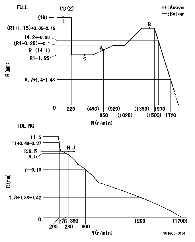
N:Pump speed
R:Rack position (mm)
(1)Torque cam stamping: T1
(2)Tolerance for racks not indicated: +-0.05mm.
----------
T1=N97
----------
----------
T1=N97
----------
Timer adjustment

(1)Adjusting range
(2)Step response time
(N): Speed of the pump
(L): Load
(theta) Advance angle
(Srd1) Step response time 1
(Srd2) Step response time 2
1. Adjusting conditions for the variable timer
(1)Adjust the clearance between the pickup and the protrusion to L.
----------
L=1.5+-0.2mm N2=800r/min C2=(8)deg t1=2--sec. t2=2--sec.
----------
N1=1300++r/min P1=0kPa(0kgf/cm2) P2=392kPa(4kgf/cm2) C1=8+-0.3deg R01=0/4load R02=4/4load
----------
L=1.5+-0.2mm N2=800r/min C2=(8)deg t1=2--sec. t2=2--sec.
----------
N1=1300++r/min P1=0kPa(0kgf/cm2) P2=392kPa(4kgf/cm2) C1=8+-0.3deg R01=0/4load R02=4/4load
Speed control lever angle
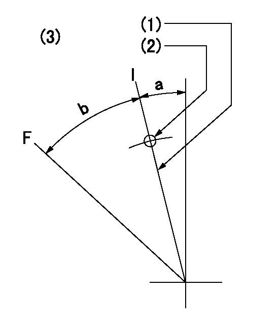
F:Full speed
I:Idle
(1)Stopper bolt set position 'H'
(2)Use the pin at R = aa
(3)Viewed from feed pump side.
----------
aa=33mm
----------
a=12deg+-5deg b=47.5deg+-3deg
----------
aa=33mm
----------
a=12deg+-5deg b=47.5deg+-3deg
Stop lever angle

N:Pump normal
S:Stop the pump.
(1)Use the pin at R = aa
----------
aa=45mm
----------
a=12.5deg+-5deg b=40deg+-5deg
----------
aa=45mm
----------
a=12.5deg+-5deg b=40deg+-5deg
0000001501 RACK SENSOR
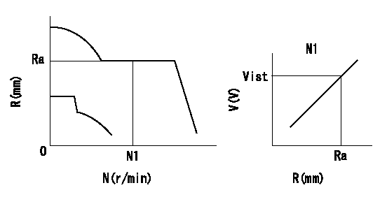
Rack sensor adjustment
1. Flange type rack sensor (rack sensor adjustment -5*20)
(1)These types of rack sensors do not need adjustment. Confirm the performance with the following procedures.
(2)Mount the rack sensor main body to the pump main body.
(3)Fix the pump lever at full.
(4)At supply voltage V1, pump speed N1 and rack position Ra, confirm that the amp's output voltage is Vist.
(5)Move the pump lever two or three times.
(6)Set again to full.
(7)Confirm that the amplifier output voltage is Vist.
(8)Fix the caution plate to the upper part of the rack sensor.
(For those without the caution plate instructions, make sure the nameplate of the rack sensor carries the "Don't hold here" caution.)
(9)Apply red paint to the rack sensor mounting bolts (2 places).
----------
V1=5+-0.01V N1=850r/min Ra=R1(14.1)mm Vist=3.55+-0.28V
----------
----------
V1=5+-0.01V N1=850r/min Ra=R1(14.1)mm Vist=3.55+-0.28V
----------
Timing setting

(1)Pump vertical direction
(2)Positions of coupling's threaded installation holes at No 1 cylinder's beginning of injection
(3)B.T.D.C.: aa
(4)-
----------
aa=6deg
----------
a=(160deg)
----------
aa=6deg
----------
a=(160deg)
Information:
Fuel Injection Nozzles
Test/Clean/Replace
The engine will be damaged if a defective fuel injection nozzle is used because of the shape of fuel (spray pattern) that comes out of the nozzles will not be correct.
Fuel injection nozzles are subject to tip wear as a result of fuel contamination. This damage can cause an increase in fuel consumption, the engine to emit black smoke, misfire or run rough. Inspect, test and replace if necessary.Whenever the engine performs in such a manner that a fuel injection nozzle is suspected of causing irregular running, smoking or knocking, each fuel injection nozzle must be isolated, one at a time, to determine the malfunctioning nozzle. Special tooling is required to remove fuel injection nozzles. Refer to the Service Manual or contact your Caterpillar dealer for fuel injection nozzle testing and cleaning procedures.Turbocharger
Periodic inspection and cleaning is recommended for the turbocharger compressor housing (inlet side) and the aftercooler core. Since the crankcase fumes are ingested through the inlet air system, oil and combustion by-products may collect in these two areas.This buildup, over time, can contribute to loss of engine power, increased black smoke, and overall loss of engine efficiency. This buildup is only a possible contributor to these conditions.Operating the engine until the turbocharger fails can severely damage the turbocharger's compressor wheel and/or the engine. Damage to the turbocharger compressor wheel could allow parts from the compressor wheel to enter the engine cylinder, causing additional damage to the piston, valve, and cylinder head.
Turbocharger bearing failures can cause large quantities of oil to enter the air inlet and exhaust systems. Loss of engine lubricant can result in serious engine damage.When a turbocharger bearing failure is accompanied by a significant engine performance loss (exhaust smoke or engine speed up at no load), DO NOT continue engine operation until the turbocharger is repaired or replaced.
Minor leakage of a turbocharger housing under extended low idle operation will not cause problems as long as no turbocharger bearing failure occurred.Inspect for Proper Operation
Turbocharger components require precision clearances and balancing due to operation at high rotational speeds. Severe Service Applications can accelerate component wear and may suggest the need to Inspect/Repair/Replace the cartridge at reduced intervals to ensure maximum reliability and retention of full core value.The following conditions can indicate severe service operation.* Frequent high altitude operation above 5,000 ft (1525 m).* Arctic operation (regular cold starts at temperatures below 0°C [32°F]).* Extending lubrication and inlet air system maintenance intervals. 1. Remove the exhaust outlet piping (1) and inlet piping (2) from the turbocharger. Visually check for oil leaks.2. Turn the compressor wheel and turbine wheel by hand. The assembly should turn freely. Inspect the compressor wheel and turbine wheel for contact with the turbocharger housing. There should NOT be any visible signs of contact between the turbine or compressor wheel and the turbocharger housing. If there is any indication of contact between the rotating wheel(s) and the housing, the turbocharger should be reconditioned or replaced.3. Use a dial indicator to check end
Have questions with 101606-0151?
Group cross 101606-0151 ZEXEL
Isuzu
101606-0151
9 400 615 407
8976004551
INJECTION-PUMP ASSEMBLY
6HL1-S
6HL1-S