Information injection-pump assembly
ZEXEL
101606-0100
1016060100
ISUZU
8976000020
8976000020
Rating:
Cross reference number
ZEXEL
101606-0100
1016060100
ISUZU
8976000020
8976000020
Zexel num
Bosch num
Firm num
Name
Calibration Data:
Adjustment conditions
Test oil
1404 Test oil ISO4113 or {SAEJ967d}
1404 Test oil ISO4113 or {SAEJ967d}
Test oil temperature
degC
40
40
45
Nozzle and nozzle holder
105780-8260
Bosch type code
9 430 610 133
Nozzle
105780-0120
Bosch type code
1 688 901 990
Nozzle holder
105780-2190
Opening pressure
MPa
18
Opening pressure
kgf/cm2
184
Injection pipe
Outer diameter - inner diameter - length (mm) mm 6-2-600
Outer diameter - inner diameter - length (mm) mm 6-2-600
Overflow valve
131424-8620
Overflow valve opening pressure
kPa
206
172
240
Overflow valve opening pressure
kgf/cm2
2.1
1.75
2.45
Tester oil delivery pressure
kPa
255
255
255
Tester oil delivery pressure
kgf/cm2
2.6
2.6
2.6
Direction of rotation (viewed from drive side)
Left L
Left L
Injection timing adjustment
Direction of rotation (viewed from drive side)
Left L
Left L
Injection order
1-5-3-6-
2-4
Pre-stroke
mm
3.8
3.75
3.85
Rack position
Point A R=A
Point A R=A
Beginning of injection position
Governor side NO.1
Governor side NO.1
Difference between angles 1
Cal 1-5 deg. 60 59.5 60.5
Cal 1-5 deg. 60 59.5 60.5
Difference between angles 2
Cal 1-3 deg. 120 119.5 120.5
Cal 1-3 deg. 120 119.5 120.5
Difference between angles 3
Cal 1-6 deg. 180 179.5 180.5
Cal 1-6 deg. 180 179.5 180.5
Difference between angles 4
Cyl.1-2 deg. 240 239.5 240.5
Cyl.1-2 deg. 240 239.5 240.5
Difference between angles 5
Cal 1-4 deg. 300 299.5 300.5
Cal 1-4 deg. 300 299.5 300.5
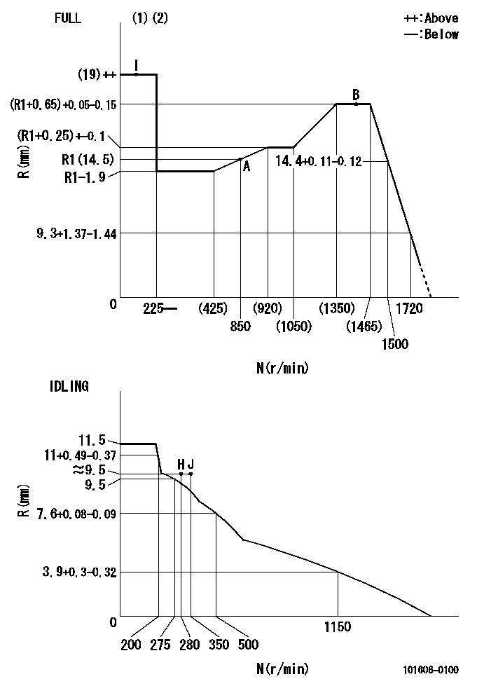
Injection quantity adjustment
Adjusting point
-
Rack position
14.5
Pump speed
r/min
850
850
850
Average injection quantity
mm3/st.
133.5
131.9
135.1
Max. variation between cylinders
%
0
-2.5
2.5
Basic
*
Fixing the rack
*
Standard for adjustment of the maximum variation between cylinders
*
Injection quantity adjustment_02
Adjusting point
Z
Rack position
9.5+-0.5
Pump speed
r/min
300
300
300
Average injection quantity
mm3/st.
15.5
14.2
16.8
Max. variation between cylinders
%
0
-14
14
Fixing the rack
*
Standard for adjustment of the maximum variation between cylinders
*
Injection quantity adjustment_03
Adjusting point
A
Rack position
R1(14.5)
Pump speed
r/min
850
850
850
Average injection quantity
mm3/st.
133.5
132.5
134.5
Basic
*
Fixing the lever
*
Injection quantity adjustment_04
Adjusting point
B
Rack position
(R1+0.65
)+0.05-0
.15
Pump speed
r/min
1450
1450
1450
Average injection quantity
mm3/st.
127
123.8
130.2
Fixing the lever
*
Test data Ex:
Governor adjustment
N:Pump speed
R:Rack position (mm)
(1)Torque cam stamping: T1
(2)Tolerance for racks not indicated: +-0.05mm.
----------
T1=N11
----------
----------
T1=N11
----------
Timer adjustment

(1)Adjusting range
(2)Step response time
(N): Speed of the pump
(L): Load
(theta) Advance angle
(Srd1) Step response time 1
(Srd2) Step response time 2
1. Adjusting conditions for the variable timer
(1)Adjust the clearance between the pickup and the protrusion to L.
----------
L=1.5+-0.2mm N2=800r/min C2=(8deg) t1=2--sec. t2=2--sec.
----------
N1=1300++r/min P1=0kPa(0kgf/cm2) P2=392kPa(4kgf/cm2) C1=8+-0.3deg R01=0/4load R02=4/4load
----------
L=1.5+-0.2mm N2=800r/min C2=(8deg) t1=2--sec. t2=2--sec.
----------
N1=1300++r/min P1=0kPa(0kgf/cm2) P2=392kPa(4kgf/cm2) C1=8+-0.3deg R01=0/4load R02=4/4load
Speed control lever angle
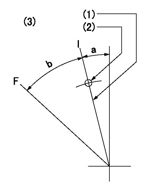
F:Full speed
I:Idle
(1)Stopper bolt set position 'H'
(2)Use the pin at R = aa
(3)Viewed from feed pump side.
----------
aa=35mm
----------
a=10deg+-5deg b=40deg+-3deg
----------
aa=35mm
----------
a=10deg+-5deg b=40deg+-3deg
Stop lever angle

N:Pump normal
S:Stop the pump.
(1)Use the pin at R = aa
----------
aa=45mm
----------
a=12.5deg+-5deg b=40deg+-5deg
----------
aa=45mm
----------
a=12.5deg+-5deg b=40deg+-5deg
0000001501 RACK SENSOR
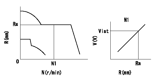
Rack sensor adjustment
1. Flange type rack sensor (rack sensor adjustment -5*20)
(1)These types of rack sensors do not need adjustment. Confirm the performance with the following procedures.
(2)Mount the rack sensor main body to the pump main body.
(3)Fix the pump lever at full.
(4)At supply voltage V1, pump speed N1 and rack position Ra, confirm that the amp's output voltage is Vist.
(5)Move the pump lever two or three times.
(6)Set again to full.
(7)Confirm that the amplifier output voltage is Vist.
(8)Fix the caution plate to the upper part of the rack sensor.
(For those without the caution plate instructions, make sure the nameplate of the rack sensor carries the "Don't hold here" caution.)
(9)Apply red paint to the rack sensor mounting bolts (2 places).
----------
V1=5+-0.01V N1=850r/min Ra=R1(14.5)mm Vist=3.74+-0.28V
----------
----------
V1=5+-0.01V N1=850r/min Ra=R1(14.5)mm Vist=3.74+-0.28V
----------
Timing setting

(1)Pump vertical direction
(2)Positions of coupling's threaded installation holes at No 1 cylinder's beginning of injection
(3)B.T.D.C.: aa
(4)-
----------
aa=6deg
----------
a=(160deg)
----------
aa=6deg
----------
a=(160deg)
Information:
Electric Starting
Startability will be improved at temperatures below 16°C (60°F) by the use of a starting aid. A jacket water (coolant) heater or other means can be used to heat the crankcase oil.Start the engine using the following procedure:1. Perform all before-starting inspections.2. If the engine is equipped with a manual control, ensure that is in the RUN position. Place the transmission in NEUTRAL (and disengage the flywheel clutch, if equipped). For Generator Sets, open the main electrical circuit breaker.2. Move throttle to approximately half engine speed to get the fuel rack to move to the FUEL ON position.3. Turn the starter switch to START (or battery disconnect switch to the ON position) or the Engine Control Switch (ECS) to MAN. START. The starting motor will crank and attempt to start the engine. At temperatures below 0°C (32°F), it may be necessary to spray starting fluid into the air cleaner inlet. Additional injections of ether may be required to start and/or achieve low idle speed.
Excessive ether can cause piston and ring damage. When using starting fluid, follow the manufacturer's instructions carefully, use it sparingly and spray it ONLY WHILE CRANKING THE ENGINE. Failure to do so could result in an explosion and/or fire and possible personal injury.Use ether for cold starting purposes only.
Do not crank the engine for more than 30 seconds.
If a warm engine fails to start within 30 seconds: release the starter switch and wait two minutes to allow the starter motor to cool before using it again.4. As soon as the engine starts, allow the engine to idle for 3 to 5 minutes, or until the water temperature gauge indicator has begun to rise. The engine should run at low idle smoothly until speed is gradually increased to high idle.
Do not increase engine speed until the oil pressure gauge indicates normal. Oil pressure should rise within 15 seconds after the engine starts. If oil pressure is not indicated on gauge within 15 seconds, stop the engine, investigate and correct the cause.
5. Allow white smoke to clear up and proceed with normal operation. Do not apply load to the engine or increase engine speed until the oil pressure gauge indicates normal. Oil pressure should raise within 15 seconds after the engine starts. For starting in cold weather, to minimize white smoke: start the engine and allow the engine to idle for 30 seconds. Increase rpm until engine speed reaches 1200 rpm. Then allow the engine to return to low idle.6. Operate the engine at low load until all systems reach operating temperature. Check all gauges during the warm-up period.Engine Starting With Jumper Cables
When boost starting an engine, follow the instructions to properly start the engine. This engine is equipped with a 12 or 24 volt starting system. Use only equal voltage for boost starting. The use of higher voltage will damage the electrical system.
Batteries give off flammable fumes that can explode.Improper jumper cable connections can cause an explosion resulting in personal injury.Prevent sparks near the batteries.