Information injection-pump assembly
ZEXEL
101606-0091
1016060091
ISUZU
8976000012
8976000012

Rating:
Service parts 101606-0091 INJECTION-PUMP ASSEMBLY:
1.
_
7.
COUPLING PLATE
8.
_
9.
_
11.
Nozzle and Holder
8-94391-291-4
12.
Open Pre:MPa(Kqf/cm2)
16.2{165}/19.6{200}
14.
NOZZLE
Cross reference number
ZEXEL
101606-0091
1016060091
ISUZU
8976000012
8976000012
Zexel num
Bosch num
Firm num
Name
Calibration Data:
Adjustment conditions
Test oil
1404 Test oil ISO4113 or {SAEJ967d}
1404 Test oil ISO4113 or {SAEJ967d}
Test oil temperature
degC
40
40
45
Nozzle and nozzle holder
105780-8260
Bosch type code
9 430 610 133
Nozzle
105780-0120
Bosch type code
1 688 901 990
Nozzle holder
105780-2190
Opening pressure
MPa
18
Opening pressure
kgf/cm2
184
Injection pipe
Outer diameter - inner diameter - length (mm) mm 6-2-600
Outer diameter - inner diameter - length (mm) mm 6-2-600
Overflow valve
131424-8620
Overflow valve opening pressure
kPa
206
172
240
Overflow valve opening pressure
kgf/cm2
2.1
1.75
2.45
Tester oil delivery pressure
kPa
255
255
255
Tester oil delivery pressure
kgf/cm2
2.6
2.6
2.6
Direction of rotation (viewed from drive side)
Left L
Left L
Injection timing adjustment
Direction of rotation (viewed from drive side)
Left L
Left L
Injection order
1-5-3-6-
2-4
Pre-stroke
mm
3.8
3.75
3.85
Rack position
Point A R=A
Point A R=A
Beginning of injection position
Governor side NO.1
Governor side NO.1
Difference between angles 1
Cal 1-5 deg. 60 59.5 60.5
Cal 1-5 deg. 60 59.5 60.5
Difference between angles 2
Cal 1-3 deg. 120 119.5 120.5
Cal 1-3 deg. 120 119.5 120.5
Difference between angles 3
Cal 1-6 deg. 180 179.5 180.5
Cal 1-6 deg. 180 179.5 180.5
Difference between angles 4
Cyl.1-2 deg. 240 239.5 240.5
Cyl.1-2 deg. 240 239.5 240.5
Difference between angles 5
Cal 1-4 deg. 300 299.5 300.5
Cal 1-4 deg. 300 299.5 300.5
Injection quantity adjustment
Adjusting point
-
Rack position
14.5
Pump speed
r/min
850
850
850
Average injection quantity
mm3/st.
133.5
131.9
135.1
Max. variation between cylinders
%
0
-2.5
2.5
Basic
*
Fixing the rack
*
Standard for adjustment of the maximum variation between cylinders
*
Injection quantity adjustment_02
Adjusting point
Z
Rack position
9.5+-0.5
Pump speed
r/min
300
300
300
Average injection quantity
mm3/st.
15.5
14.2
16.8
Max. variation between cylinders
%
0
-14
14
Fixing the rack
*
Standard for adjustment of the maximum variation between cylinders
*
Injection quantity adjustment_03
Adjusting point
A
Rack position
R1(14.5)
Pump speed
r/min
850
850
850
Average injection quantity
mm3/st.
133.5
132.5
134.5
Basic
*
Fixing the lever
*
Injection quantity adjustment_04
Adjusting point
B
Rack position
(R1+1.05
)+0.05-0
.15
Pump speed
r/min
1450
1450
1450
Average injection quantity
mm3/st.
133
129.8
136.2
Fixing the lever
*
Test data Ex:
Governor adjustment
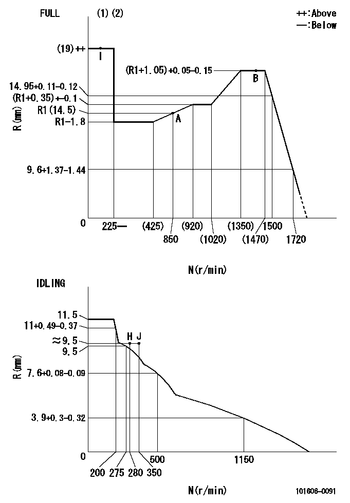
N:Pump speed
R:Rack position (mm)
(1)Torque cam stamping: T1
(2)Tolerance for racks not indicated: +-0.05mm.
----------
T1=N14
----------
----------
T1=N14
----------
Timer adjustment
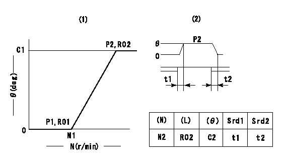
(1)Adjusting range
(2)Step response time
(N): Speed of the pump
(L): Load
(theta) Advance angle
(Srd1) Step response time 1
(Srd2) Step response time 2
1. Adjusting conditions for the variable timer
(1)Adjust the clearance between the pickup and the protrusion to L.
----------
L=1.5+-0.2mm N2=800r/min C2=(8deg) t1=2--sec. t2=2--sec.
----------
N1=1300++r/min P1=0kPa(0kgf/cm2) P2=392kPa(4kgf/cm2) C1=8+-0.3deg R01=0/4load R02=4/4load
----------
L=1.5+-0.2mm N2=800r/min C2=(8deg) t1=2--sec. t2=2--sec.
----------
N1=1300++r/min P1=0kPa(0kgf/cm2) P2=392kPa(4kgf/cm2) C1=8+-0.3deg R01=0/4load R02=4/4load
Speed control lever angle
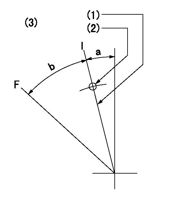
F:Full speed
I:Idle
(1)Stopper bolt set position 'H'
(2)Use the pin at R = aa
(3)Viewed from feed pump side.
----------
aa=35mm
----------
a=10deg+-5deg b=41deg+-3deg
----------
aa=35mm
----------
a=10deg+-5deg b=41deg+-3deg
Stop lever angle
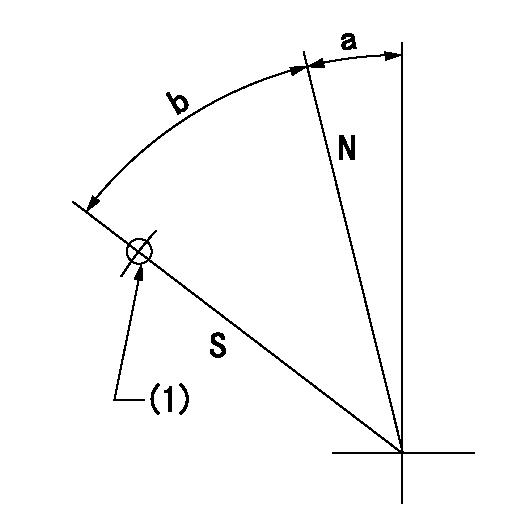
N:Pump normal
S:Stop the pump.
(1)Use the pin at R = aa
----------
aa=45mm
----------
a=12.5deg+-5deg b=40deg+-5deg
----------
aa=45mm
----------
a=12.5deg+-5deg b=40deg+-5deg
0000001501 RACK SENSOR
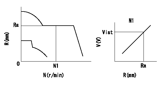
Rack sensor adjustment
1. Flange type rack sensor (rack sensor adjustment -5*20)
(1)These types of rack sensors do not need adjustment. Confirm the performance with the following procedures.
(2)Mount the rack sensor main body to the pump main body.
(3)Fix the pump lever at full.
(4)At supply voltage V1, pump speed N1 and rack position Ra, confirm that the amp's output voltage is Vist.
(5)Move the pump lever two or three times.
(6)Set again to full.
(7)Confirm that the amplifier output voltage is Vist.
(8)Fix the caution plate to the upper part of the rack sensor.
(For those without the caution plate instructions, make sure the nameplate of the rack sensor carries the "Don't hold here" caution.)
(9)Apply red paint to the rack sensor mounting bolts (2 places).
----------
V1=5+-0.01V N1=850r/min Ra=R1(14.5)mm Vist=3.74+-0.28V
----------
----------
V1=5+-0.01V N1=850r/min Ra=R1(14.5)mm Vist=3.74+-0.28V
----------
Timing setting
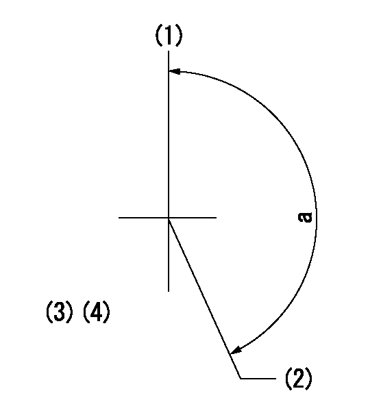
(1)Pump vertical direction
(2)Positions of coupling's threaded installation holes at No 1 cylinder's beginning of injection
(3)B.T.D.C.: aa
(4)-
----------
aa=6deg
----------
a=(160deg)
----------
aa=6deg
----------
a=(160deg)
Information:
Total Base Number (TBN) and Fuel Sulfur Levels For Caterpillar DI Diesel Engines
The TBN required in a new oil depends on the sulfur level of the fuel used. For direct injection engines running on distillate diesel fuel, the minimum new oil TBN (by ASTM D2896) should be 10 times the fuel sulfur level, and the minimum TBN is 5 regardless of a low fuel sulfur level- refer to the following graph.
Y = oil TBN shown by ASTM D2896.
X = percent of fuel sulfur by weight.
New oil TBN (1).
Change oil when the used oil TBN limit (2) is reached.In areas where the fuel sulfur exceeds 1.5 percent, choose an oil with the highest TBN that is within the API CF-4 or CG-4 categories, and shorten the oil change interval based on oil analysis. The oil analysis should evaluate oil condition and wear metals. High TBN oils that are not within the API CF-4 or CG-4 categories can produce excessive piston deposits, leading to a loss of oil control and bore polishing.
Operating DI diesel engines with fuel sulfur levels over 1.0 percent may require shortened oil change intervals in order to maintain adequate wear protection.
Lubricant Viscosity Recommendations For Caterpillar DI Engines
The proper SAE viscosity grade oil is determined by the minimum outside temperature at cold engine start-up, and the maximum outside temperature during engine operation. Use the minimum temperature column on the chart to determine the oil viscosity required for starting a "cold soaked" engine. Use the maximum temperature column on the chart to select the viscosity for operation at the highest temperature anticipated. In general, use the highest viscosity oil available that still meets the start-up temperature requirements. Engine Lubricant Recommendations Summary
To achieve all the performance that was built into a Caterpillar engine, follow these guidelines: * Select the proper Caterpillar oil or commercial oil that meets the API specifications* Select the proper oil viscosity based on the applicable Lubricant Viscosities chart* Replace the engine oil and oil filter(s) at the intervals specified in the Operation and Maintenance Manual* Perform maintenance according to the Operation and Maintenance ManualCaterpillar Lubricating Grease
Caterpillar provides grease for a variety of applications and extreme temperature conditions. The descriptions of these products follow.Contact your Caterpillar dealer for part numbers and available container sizes. One grease may be incompatible with another grease. When using commercial grease, make sure the grease is compatible with the grease used in your system, or make sure to purge the system. Contact your supplier regarding grease compatibility questions.Multipurpose Grease
Multipurpose Lithium Complex Grease (MPG)
MPG is a NLGI No.2 general purpose lithium complex grease for light to medium duty applications. MPG has good high temperature characteristics, with a minimum dropping point of 260°C (500°F). MPG contains unleaded extreme pressure additives and antiwear and corrosion inhibitors to provide extra protection in a variety of construction, agricultural and automotive applications.MPG meets the requirements for extended service intervals of automotive chassis points and wheel bearings with disc brakes, particularly in passenger cars, vans, light trucks and