Information injection-pump assembly
ZEXEL
101606-0060
1016060060
ISUZU
8943928380
8943928380
Rating:
Cross reference number
ZEXEL
101606-0060
1016060060
ISUZU
8943928380
8943928380
Zexel num
Bosch num
Firm num
Name
Calibration Data:
Adjustment conditions
Test oil
1404 Test oil ISO4113 or {SAEJ967d}
1404 Test oil ISO4113 or {SAEJ967d}
Test oil temperature
degC
40
40
45
Nozzle and nozzle holder
105780-8260
Bosch type code
9 430 610 133
Nozzle
105780-0120
Bosch type code
1 688 901 990
Nozzle holder
105780-2190
Opening pressure
MPa
18
Opening pressure
kgf/cm2
184
Injection pipe
Outer diameter - inner diameter - length (mm) mm 6-2-600
Outer diameter - inner diameter - length (mm) mm 6-2-600
Overflow valve
131424-8620
Overflow valve opening pressure
kPa
206
172
240
Overflow valve opening pressure
kgf/cm2
2.1
1.75
2.45
Tester oil delivery pressure
kPa
255
255
255
Tester oil delivery pressure
kgf/cm2
2.6
2.6
2.6
Direction of rotation (viewed from drive side)
Left L
Left L
Injection timing adjustment
Direction of rotation (viewed from drive side)
Left L
Left L
Injection order
1-5-3-6-
2-4
Pre-stroke
mm
3.8
3.75
3.85
Rack position
Point A R=A
Point A R=A
Beginning of injection position
Governor side NO.1
Governor side NO.1
Difference between angles 1
Cal 1-5 deg. 60 59.5 60.5
Cal 1-5 deg. 60 59.5 60.5
Difference between angles 2
Cal 1-3 deg. 120 119.5 120.5
Cal 1-3 deg. 120 119.5 120.5
Difference between angles 3
Cal 1-6 deg. 180 179.5 180.5
Cal 1-6 deg. 180 179.5 180.5
Difference between angles 4
Cyl.1-2 deg. 240 239.5 240.5
Cyl.1-2 deg. 240 239.5 240.5
Difference between angles 5
Cal 1-4 deg. 300 299.5 300.5
Cal 1-4 deg. 300 299.5 300.5
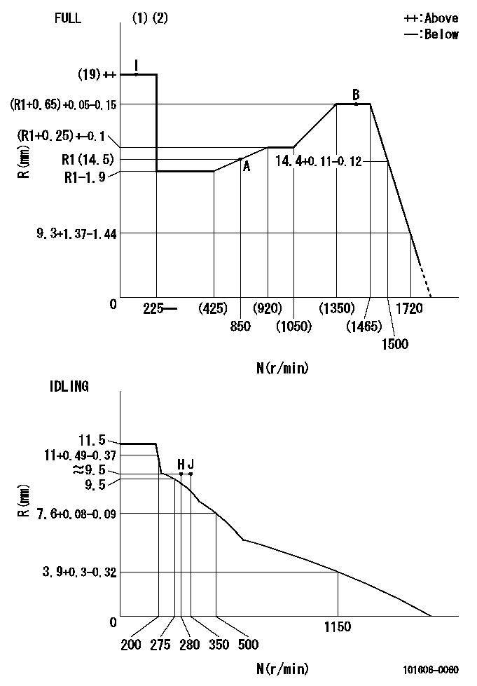
Injection quantity adjustment
Adjusting point
-
Rack position
14.5
Pump speed
r/min
850
850
850
Average injection quantity
mm3/st.
133.5
131.9
135.1
Max. variation between cylinders
%
0
-2.5
2.5
Basic
*
Fixing the rack
*
Standard for adjustment of the maximum variation between cylinders
*
Injection quantity adjustment_02
Adjusting point
Z
Rack position
9.5+-0.5
Pump speed
r/min
300
300
300
Average injection quantity
mm3/st.
15.5
14.2
16.8
Max. variation between cylinders
%
0
-14
14
Fixing the rack
*
Standard for adjustment of the maximum variation between cylinders
*
Injection quantity adjustment_03
Adjusting point
A
Rack position
R1(14.5)
Pump speed
r/min
850
850
850
Average injection quantity
mm3/st.
133.5
132.5
134.5
Basic
*
Fixing the lever
*
Injection quantity adjustment_04
Adjusting point
B
Rack position
(R1+0.65
)+0.05-0
.15
Pump speed
r/min
1450
1450
1450
Average injection quantity
mm3/st.
127
123.8
130.2
Fixing the lever
*
Test data Ex:
Governor adjustment
N:Pump speed
R:Rack position (mm)
(1)Torque cam stamping: T1
(2)Tolerance for racks not indicated: +-0.05mm.
----------
T1=N11
----------
----------
T1=N11
----------
Timer adjustment

(1)Adjusting range
(2)Step response time
(N): Speed of the pump
(L): Load
(theta) Advance angle
(Srd1) Step response time 1
(Srd2) Step response time 2
1. Adjusting conditions for the variable timer
(1)Adjust the clearance between the pickup and the protrusion to L.
----------
L=1.5+-0.2mm N2=800r/min C2=(8deg) t1=2--sec. t2=2--sec.
----------
N1=1300++r/min P1=0kPa(0kgf/cm2) P2=392kPa(4kgf/cm2) C1=8+-0.3deg R01=0/4load R02=4/4load
----------
L=1.5+-0.2mm N2=800r/min C2=(8deg) t1=2--sec. t2=2--sec.
----------
N1=1300++r/min P1=0kPa(0kgf/cm2) P2=392kPa(4kgf/cm2) C1=8+-0.3deg R01=0/4load R02=4/4load
Speed control lever angle
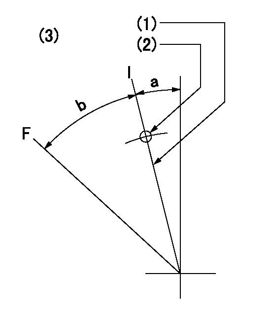
F:Full speed
I:Idle
(1)Stopper bolt set position 'H'
(2)Use the pin at R = aa
(3)Viewed from feed pump side.
----------
aa=35mm
----------
a=10deg+-5deg b=40deg+-3deg
----------
aa=35mm
----------
a=10deg+-5deg b=40deg+-3deg
Stop lever angle

N:Pump normal
S:Stop the pump.
(1)Use the pin at R = aa
----------
aa=45mm
----------
a=12.5deg+-5deg b=40deg+-5deg
----------
aa=45mm
----------
a=12.5deg+-5deg b=40deg+-5deg
0000001501 RACK SENSOR
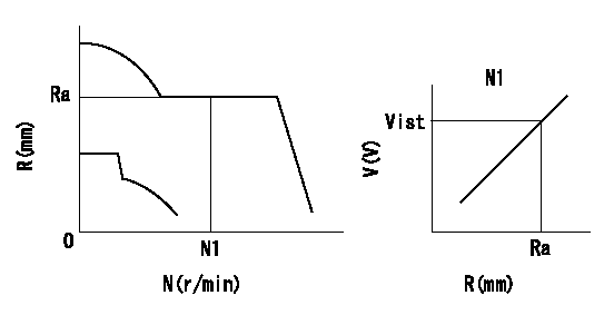
Rack sensor adjustment
1. Flange type rack sensor (rack sensor adjustment -5*20)
(1)These types of rack sensors do not need adjustment. Confirm the performance with the following procedures.
(2)Mount the rack sensor main body to the pump main body.
(3)Fix the pump lever at full.
(4)At supply voltage V1, pump speed N1 and rack position Ra, confirm that the amp's output voltage is Vist.
(5)Move the pump lever two or three times.
(6)Set again to full.
(7)Confirm that the amplifier output voltage is Vist.
(8)Fix the caution plate to the upper part of the rack sensor.
(For those without the caution plate instructions, make sure the nameplate of the rack sensor carries the "Don't hold here" caution.)
(9)Apply red paint to the rack sensor mounting bolts (2 places).
----------
V1=5+-0.01V N1=850r/min Ra=R1(14.5)mm Vist=3.74+-0.28V
----------
----------
V1=5+-0.01V N1=850r/min Ra=R1(14.5)mm Vist=3.74+-0.28V
----------
Timing setting

(1)Pump vertical direction
(2)Positions of coupling's threaded installation holes at No 1 cylinder's beginning of injection
(3)B.T.D.C.: aa
(4)-
----------
aa=6deg
----------
a=(160deg)
----------
aa=6deg
----------
a=(160deg)
Information:
Caterpillar Reference MaterialSEBD0518 Know Your Cooling SystemSEBD0640 Oil and Your EngineSEBD0717 Diesel Fuels and Your EngineSEBD0970 Coolant and Your EngineSEBU5898 Cold Weather Recommendations Operation and Maintenance ManualSEBU6310 EMA Engine Oil Data BookSEHS7067 Fuels for Caterpillar Diesel EnginesSEHS7808 Special Instruction-6V3060 Low Emission System TesterSEHS8622 Using the FT1984 Air-To-Air Aftercooler Leak Test GroupSELF5052 Emission Related Components WarrantyLEDT5092 Driving Techniques For Maximum Fuel EconomyLEBT8121 Truck Engine Application and Installation GuideLEGT5087 Truck Engine Application and Installation GuideLEKQ3363 Caterpillar Engine Data Sheet 60.1 - "Fuels Recommended For Use In Caterpillar Truck Engines"LEXT7056 Performance Analysis Report (PAR) Testing for 3406B PEEC Truck EnginesSEHS9031 Storage Procedure for Caterpillar ProductsSENRXXXX 3406B PEEC Service Manual (8TC1 and Up, 5YG1-UP) (Contact your Caterpillar dealer for the correct Service Manual for your engine).SEBR0514 Low Emission SystemSEBF8029 Index to Guidelines for Reusable Parts and Salvage OperationsSEBF8062 Guideline for Reusable Parts - Cleaning and Inspection of Air FiltersSEBD0794 3400 Engine-Major Component Performance GuidePEDP7122 Question & Answer BookletPEHP7504 CAT Engine Oil Spec SheetsPEHP7505 CAT Diesel Engine Oil Spec SheetsAll of the above publications are available through your Caterpillar dealer. The following Special Instructions pertain to the operation, maintenance, diagnostic tooling and programming of the PEEC system. Some of these publications will be included in the tool kits, the others will be available thru your Caterpillar dealer.SEHS8741 Using the 8C5919 3406B PEEC Service Program ModuleSEHS8742 Using the 8T8697 Electronic Control Analyzer Programmer (ECAP)SEHS8743 Using the 8C4629 Digital Diagnostic Tool DDT with the 3406B Programmable Electronic Engine Control PEEC ModuleSEHS8746 Using the 1U5540 Tool GroupSEHS8747 PEEC Screen Map(s).All of the above publications are available through your Caterpillar dealer. Additional Reference MaterialASTM D217-68 - Worked PenetrationASTM D2896 TBN MeasurementsASTM Specs can normally be obtained from your local technological society, library or college.SAE J313 Diesel FuelsSAE J754 NomenclatureSAE J183 ClassificationSAE Specs can be found in your SAE handbook or can be obtained from your local library, college or technological society.