Information injection-pump assembly
BOSCH
9 400 615 401
9400615401
ZEXEL
101606-0012
1016060012
ISUZU
8943921082
8943921082
Rating:
Include in #2:
104746-1520
as _
Cross reference number
BOSCH
9 400 615 401
9400615401
ZEXEL
101606-0012
1016060012
ISUZU
8943921082
8943921082
Zexel num
Bosch num
Firm num
Name
101606-0012
9 400 615 401
8943921082 ISUZU
INJECTION-PUMP ASSEMBLY
6HH1 K 14BE INJECTION PUMP ASSY PE6A PE
6HH1 K 14BE INJECTION PUMP ASSY PE6A PE
Calibration Data:
Adjustment conditions
Test oil
1404 Test oil ISO4113 or {SAEJ967d}
1404 Test oil ISO4113 or {SAEJ967d}
Test oil temperature
degC
40
40
45
Nozzle and nozzle holder
105780-8140
Bosch type code
EF8511/9A
Nozzle
105780-0000
Bosch type code
DN12SD12T
Nozzle holder
105780-2080
Bosch type code
EF8511/9
Opening pressure
MPa
17.2
Opening pressure
kgf/cm2
175
Injection pipe
Outer diameter - inner diameter - length (mm) mm 6-2-600
Outer diameter - inner diameter - length (mm) mm 6-2-600
Overflow valve
131424-4920
Overflow valve opening pressure
kPa
127
107
147
Overflow valve opening pressure
kgf/cm2
1.3
1.1
1.5
Tester oil delivery pressure
kPa
157
157
157
Tester oil delivery pressure
kgf/cm2
1.6
1.6
1.6
Direction of rotation (viewed from drive side)
Left L
Left L
Injection timing adjustment
Direction of rotation (viewed from drive side)
Left L
Left L
Injection order
1-5-3-6-
2-4
Pre-stroke
mm
4.2
4.15
4.25
Beginning of injection position
Governor side NO.1
Governor side NO.1
Difference between angles 1
Cal 1-5 deg. 60 59.5 60.5
Cal 1-5 deg. 60 59.5 60.5
Difference between angles 2
Cal 1-3 deg. 120 119.5 120.5
Cal 1-3 deg. 120 119.5 120.5
Difference between angles 3
Cal 1-6 deg. 180 179.5 180.5
Cal 1-6 deg. 180 179.5 180.5
Difference between angles 4
Cyl.1-2 deg. 240 239.5 240.5
Cyl.1-2 deg. 240 239.5 240.5
Difference between angles 5
Cal 1-4 deg. 300 299.5 300.5
Cal 1-4 deg. 300 299.5 300.5
Injection quantity adjustment
Adjusting point
-
Rack position
10.9
Pump speed
r/min
850
850
850
Average injection quantity
mm3/st.
71
69.4
72.6
Max. variation between cylinders
%
0
-2.5
2.5
Basic
*
Fixing the rack
*
Standard for adjustment of the maximum variation between cylinders
*
Injection quantity adjustment_02
Adjusting point
-
Rack position
9.6+-0.5
Pump speed
r/min
275
275
275
Average injection quantity
mm3/st.
9.4
8.1
10.7
Max. variation between cylinders
%
0
-14
14
Fixing the rack
*
Standard for adjustment of the maximum variation between cylinders
*
Remarks
Adjust only variation between cylinders; adjust governor according to governor specifications.
Adjust only variation between cylinders; adjust governor according to governor specifications.
Injection quantity adjustment_03
Adjusting point
A
Rack position
R1(10.9)
Pump speed
r/min
850
850
850
Average injection quantity
mm3/st.
71
70
72
Basic
*
Fixing the lever
*
Injection quantity adjustment_04
Adjusting point
B
Rack position
R1+0.45
Pump speed
r/min
1425
1425
1425
Average injection quantity
mm3/st.
87.5
83.5
91.5
Fixing the lever
*
Injection quantity adjustment_05
Adjusting point
C
Rack position
R1
Pump speed
r/min
600
600
600
Average injection quantity
mm3/st.
57
53.8
60.2
Fixing the lever
*
Injection quantity adjustment_06
Adjusting point
I
Rack position
-
Pump speed
r/min
150
150
150
Average injection quantity
mm3/st.
125
125
133
Fixing the lever
*
Rack limit
*
Timer adjustment
Pump speed
r/min
550--
Advance angle
deg.
0
0
0
Remarks
Start
Start
Timer adjustment_02
Pump speed
r/min
500
Advance angle
deg.
0.5
Timer adjustment_03
Pump speed
r/min
1000
Advance angle
deg.
3
2.5
3.5
Remarks
Finish
Finish
Test data Ex:
Governor adjustment
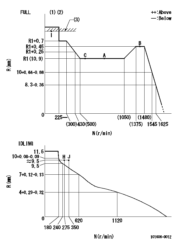
N:Pump speed
R:Rack position (mm)
(1)Torque cam stamping: T1
(2)Tolerance for racks not indicated: +-0.05mm.
(3)RACK LIMIT
----------
T1=K77
----------
----------
T1=K77
----------
Speed control lever angle
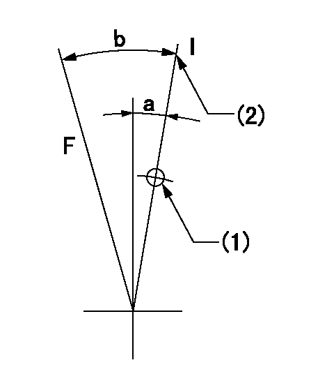
F:Full speed
I:Idle
(1)Use the hole at R = aa
(2)Stopper bolt setting
----------
aa=35mm
----------
a=14deg+-5deg b=35deg+-3deg
----------
aa=35mm
----------
a=14deg+-5deg b=35deg+-3deg
Stop lever angle
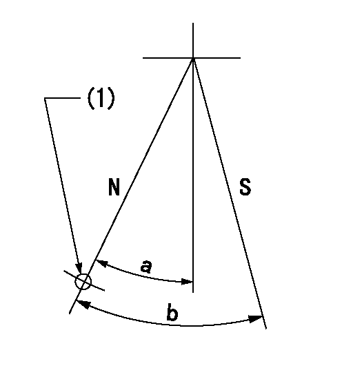
N:Pump normal
S:Stop the pump.
(1)Use the hole at R = aa
----------
aa=46.5mm
----------
a=34.5deg+-5deg b=40deg+-5deg
----------
aa=46.5mm
----------
a=34.5deg+-5deg b=40deg+-5deg
0000001501 AIR CYLINDER
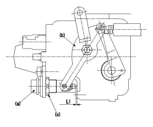
(a) Air cylinder
(b) Speed lever
(c) Lock nut
1. Air cylinder adjustment procedure
(1)Fix the speed lever (b) at the idle side.
(2)Screw in the air cylinder (a)
(3)Set the clearance between the speed lever (b) and the air cylinder (a) to approximately L1.
----------
L1=1mm
----------
----------
L1=1mm
----------
Timing setting

(1)Pump vertical direction
(2)Position of timer's threaded hole at No 1 cylinder's beginning of injection
(3)B.T.D.C.: aa
(4)-
----------
aa=14deg
----------
a=(160deg)
----------
aa=14deg
----------
a=(160deg)
Information:
Fuel System Information
Use only fuel as recommended in this section.
Fill the fuel tank at the end of each day of operation to drive out moist air and to prevent condensation. Do not fill the tank to the top. Fuel expands as it gets warm and may overflow. Do not fill the fuel filters with fuel before installing them. Contaminated fuel will cause accelerated wear to the fuel system parts.
Fuel Tanks
Drain the water and sediment from any fuel storage tank weekly, at the oil change period, and before it is refilled. This will help prevent water and/or sediment from being pumped from the fuel storage tank into the engine fuel tank.Fuel tanks should contain some provision for draining water and sediment from the bottom of the fuel tanks. Some fuel tanks use supply pipes that allow water and sediment to settle below the end of the fuel supply pipe. This water and sediment should be drained at each oil change. Do not use fuel tanks with supply lines that take fuel directly from the bottom of the tank.Fuel Lines
The fuel return line should deposit fuel at the top of the tank opposite the supply connection. This allows the engine to get warm (not hot) fuel from the tank. It also allows air to escape from the return fuel without being pulled back into the engine. If hot fuel must return to the tank, a fuel cooler is required.Avoid sharp angles and use as few fittings and connections as possible. Moisture in the fuel will tend to collect and freeze at low points in the fuel lines. Fuel lines should travel the most direct route to the engine compartment.Do not use galvanized fittings in the fuel lines. Size fuel lines so they do not exceed maximum fuel transfer pump inlet restriction and fuel return line restriction specifications.Fuel Filters
A primary fuel filter and/or water separator is recommended and should be installed between the fuel tank and the engine fuel inlet.After changing the fuel filter(s), always prime the fuel system (if equipped with a priming pump) to remove air bubbles from the system.Fuel Recommendations
Caterpillar Diesel Engines are capable of burning a wide range of distillate fuels. The use of clean, stable blends of distillate fuel which meet the following requirements will provide quality engine service life. The fuels recommended for use in Caterpillar engines are normally No.2-D diesel fuel and No.2 fuel oil, although No. 1 grades are acceptable. The following fuel specifications are some of the worldwide fuels which also meet the requirements. The following fuel characteristics should be considered when procuring fuel for use in Caterpillar diesel engines.Cetane Number
The minimum cetane number required for average starting conditions for the direct injection engine is 40. A higher cetane value may be required for high altitude operation or cold weather starting.Filterability
Clean fuels should have no more than 0.1% of sediment and water. Storage of fuel for extended periods of time can cause fuel oxidation with solids forming, causing filtering problems.Pour Point
The pour
Have questions with 101606-0012?
Group cross 101606-0012 ZEXEL
Isuzu
101606-0012
9 400 615 401
8943921082
INJECTION-PUMP ASSEMBLY
6HH1
6HH1