Information injection-pump assembly
ZEXEL
101606-0011
1016060011
ISUZU
8943921081
8943921081

Rating:
Cross reference number
ZEXEL
101606-0011
1016060011
ISUZU
8943921081
8943921081
Zexel num
Bosch num
Firm num
Name
Calibration Data:
Adjustment conditions
Test oil
1404 Test oil ISO4113 or {SAEJ967d}
1404 Test oil ISO4113 or {SAEJ967d}
Test oil temperature
degC
40
40
45
Nozzle and nozzle holder
105780-8140
Bosch type code
EF8511/9A
Nozzle
105780-0000
Bosch type code
DN12SD12T
Nozzle holder
105780-2080
Bosch type code
EF8511/9
Opening pressure
MPa
17.2
Opening pressure
kgf/cm2
175
Injection pipe
Outer diameter - inner diameter - length (mm) mm 6-2-600
Outer diameter - inner diameter - length (mm) mm 6-2-600
Overflow valve
131424-4920
Overflow valve opening pressure
kPa
127
107
147
Overflow valve opening pressure
kgf/cm2
1.3
1.1
1.5
Tester oil delivery pressure
kPa
157
157
157
Tester oil delivery pressure
kgf/cm2
1.6
1.6
1.6
Direction of rotation (viewed from drive side)
Left L
Left L
Injection timing adjustment
Direction of rotation (viewed from drive side)
Left L
Left L
Injection order
1-5-3-6-
2-4
Pre-stroke
mm
4.2
4.15
4.25
Beginning of injection position
Governor side NO.1
Governor side NO.1
Difference between angles 1
Cal 1-5 deg. 60 59.5 60.5
Cal 1-5 deg. 60 59.5 60.5
Difference between angles 2
Cal 1-3 deg. 120 119.5 120.5
Cal 1-3 deg. 120 119.5 120.5
Difference between angles 3
Cal 1-6 deg. 180 179.5 180.5
Cal 1-6 deg. 180 179.5 180.5
Difference between angles 4
Cyl.1-2 deg. 240 239.5 240.5
Cyl.1-2 deg. 240 239.5 240.5
Difference between angles 5
Cal 1-4 deg. 300 299.5 300.5
Cal 1-4 deg. 300 299.5 300.5
Injection quantity adjustment
Adjusting point
-
Rack position
10.9
Pump speed
r/min
850
850
850
Average injection quantity
mm3/st.
71
69.4
72.6
Max. variation between cylinders
%
0
-2.5
2.5
Basic
*
Fixing the rack
*
Standard for adjustment of the maximum variation between cylinders
*
Injection quantity adjustment_02
Adjusting point
-
Rack position
9.6+-0.5
Pump speed
r/min
275
275
275
Average injection quantity
mm3/st.
9.4
8.1
10.7
Max. variation between cylinders
%
0
-14
14
Fixing the rack
*
Standard for adjustment of the maximum variation between cylinders
*
Remarks
Adjust only variation between cylinders; adjust governor according to governor specifications.
Adjust only variation between cylinders; adjust governor according to governor specifications.
Injection quantity adjustment_03
Adjusting point
A
Rack position
R1(10.9)
Pump speed
r/min
850
850
850
Average injection quantity
mm3/st.
71
70
72
Basic
*
Fixing the lever
*
Injection quantity adjustment_04
Adjusting point
B
Rack position
R1+0.45
Pump speed
r/min
1425
1425
1425
Average injection quantity
mm3/st.
87.5
83.5
91.5
Fixing the lever
*
Injection quantity adjustment_05
Adjusting point
C
Rack position
R1
Pump speed
r/min
600
600
600
Average injection quantity
mm3/st.
57
53.8
60.2
Fixing the lever
*
Injection quantity adjustment_06
Adjusting point
I
Rack position
-
Pump speed
r/min
150
150
150
Average injection quantity
mm3/st.
125
125
133
Fixing the lever
*
Rack limit
*
Timer adjustment
Pump speed
r/min
550--
Advance angle
deg.
0
0
0
Remarks
Start
Start
Timer adjustment_02
Pump speed
r/min
500
Advance angle
deg.
0.5
Timer adjustment_03
Pump speed
r/min
1000
Advance angle
deg.
3
2.5
3.5
Remarks
Finish
Finish
Test data Ex:
Governor adjustment
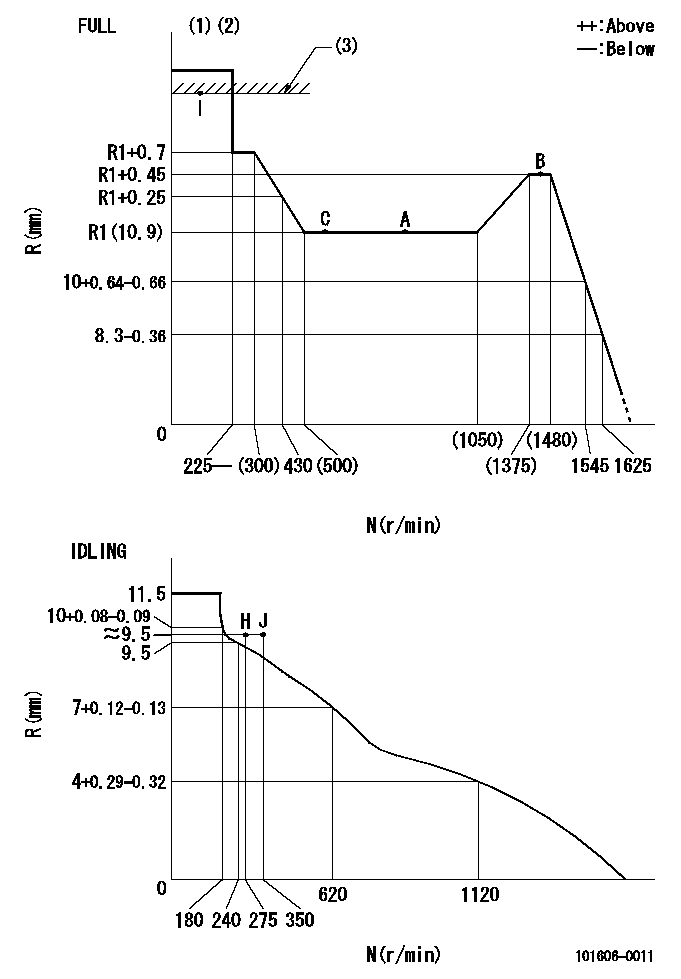
N:Pump speed
R:Rack position (mm)
(1)Torque cam stamping: T1
(2)Tolerance for racks not indicated: +-0.05mm.
(3)RACK LIMIT
----------
T1=K77
----------
----------
T1=K77
----------
Speed control lever angle
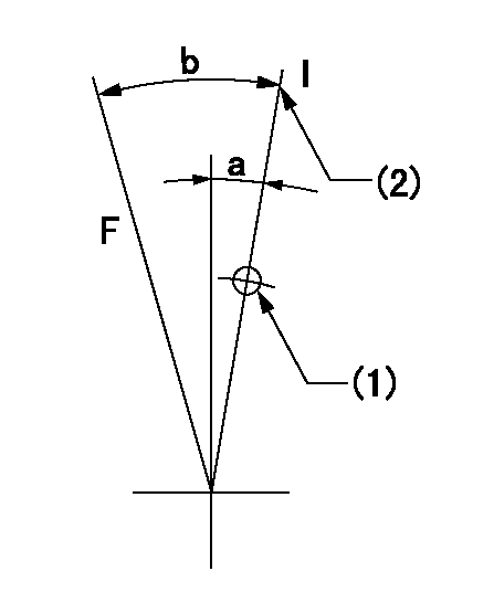
F:Full speed
I:Idle
(1)Use the hole at R = aa
(2)Stopper bolt setting
----------
aa=35mm
----------
a=14deg+-5deg b=35deg+-3deg
----------
aa=35mm
----------
a=14deg+-5deg b=35deg+-3deg
Stop lever angle
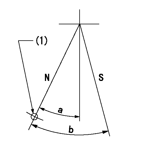
N:Pump normal
S:Stop the pump.
(1)Use the pin at R = aa
----------
aa=46.5mm
----------
a=34.5deg+-5deg b=40deg+-5deg
----------
aa=46.5mm
----------
a=34.5deg+-5deg b=40deg+-5deg
0000001501 AIR CYLINDER

1. (1) Set the speed lever to idle.
(2)Screw in air cylinder (A)
(3)Set the clearance from the speed lever (B) at approximately L.
----------
L=1mm
----------
----------
L=1mm
----------
Timing setting

(1)Pump vertical direction
(2)Position of timer's threaded hole at No 1 cylinder's beginning of injection
(3)B.T.D.C.: aa
(4)-
----------
aa=14deg
----------
a=(160deg)
----------
aa=14deg
----------
a=(160deg)
Information:
Using water that meets the minimum acceptable water requirement may not prevent drop-out of these chemical compounds totally, but should minimize the rate to acceptable levels.To determine water characteristics, contact local water department, agricultural agent or an independent laboratory to perform the testing service. Two companies are listed below. However, there are others who are qualified to provide this service.L.O.C.C. Corp.
905 Bayshore Drive
Coos Bay, OR 97420
Ph. (503) 267-4904
NALCO Chemical Co.
Naperville Technical Center
One Nalco Center
Naperville, IL 60566
Attn: Sample Receiving
Ph. (312) 961-9500
Antifreeze
Caterpillar recommends that the coolant mix contain a minimum of 30% Caterpillar Antifreeze, or equivalent and acceptable water to maintain an adequate water pump cavitation temperature for efficient water pump performance.
Premix coolant solution to provide protection to the lowest expected outside (ambient) temperature. Pure undiluted antifreeze will freeze at- 10°F (-23°C).Only use a greater concentration (above 30%) of Caterpillar Antifreeze as needed for anticipated outside (ambient) temperatures. Do not exceed a coolant mixture of 60% antifreeze to water since a concentration above 60% antifreeze will reduce the engine's freeze protection and increase the possibility of deposit formation in the cooling system.Use Caterpillar Antifreeze or ASTM D4985-89 (GM Specification 6038-M) Antifreeze. Caterpillar Antifreeze is available through your Caterpillar dealer in quantities that follow. Most commercial antifreezes are formulated for gasoline engine applications and will, therefore, have high silicate content. Caterpillar Antifreeze is formulated with a low silicate content and the proper coolant additives for heavy duty diesel engines.ASTM D4985-89 (GM Specification 6038-M) is a low silicate antifreeze, but supplemental coolant additive must be added.The major advantages of Caterpillar Antifreeze are: * Significantly reduces water pump seal leakage problems caused by excessive concentration of chemical additives.* There is no need to add supplemental coolant additive on initial fill which must be done with current commercially available antifreezes.* High silicate antifreezes used with a supplemental coolant additive can cause a build-up of solids over a period of time which can cause plugging, loss of heat transfer, and water pump seal damage. Make proper antifreeze additions.Adding pure antifreeze as a makeup solution for cooling system top-up is an unacceptable practice. It increases the concentration of antifreeze in the cooling system which increases the concentration of dissolved solids and undissolved chemical inhibitors in the cooling system. Add antifreeze mixed with water to the same freeze protection as your cooling system.Use the chart below to assist in determining the concentration of Caterpillar Antifreeze to use.
5P0957 Coolant Tester (°F) or 5P3514 Coolant Tester (°C)Both are available at your Caterpillar dealer.Check the coolant solution frequently in cold weather for glycol concentration with the 5P0957 or 5P3514 Coolant Tester to ensure adequate protection. Both testers are identical except temperature scale. They give immediate, accurate readings and can be used for antifreeze/coolants that contain ethylene or propylene glycol.If propylene glycol based antifreeze is used, DO NOT allow concentration greater than a 50/50 antifreeze to water mixture. The measurement of freeze protection must be made with a refractive-type tester (Cat 5P0957 or 5P3514) rather than a hydrometer-type, which can be