Information injection-pump assembly
BOSCH
9 400 610 706
9400610706
ZEXEL
101605-9570
1016059570
NISSAN-DIESEL
1671295005
1671295005
Rating:
Service parts 101605-9570 INJECTION-PUMP ASSEMBLY:
1.
_
5.
AUTOM. ADVANCE MECHANIS
7.
COUPLING PLATE
8.
_
9.
_
11.
Nozzle and Holder
16600-95015
12.
Open Pre:MPa(Kqf/cm2)
19.6{200}
15.
NOZZLE SET
Include in #1:
101605-9570
as INJECTION-PUMP ASSEMBLY
Include in #2:
104134-1031
as _
Cross reference number
BOSCH
9 400 610 706
9400610706
ZEXEL
101605-9570
1016059570
NISSAN-DIESEL
1671295005
1671295005
Zexel num
Bosch num
Firm num
Name
101605-9570
9 400 610 706
1671295005 NISSAN-DIESEL
INJECTION-PUMP ASSEMBLY
NE6T15 K 14BE INJECTION PUMP ASSY PE6A PE
NE6T15 K 14BE INJECTION PUMP ASSY PE6A PE
Calibration Data:
Adjustment conditions
Test oil
1404 Test oil ISO4113 or {SAEJ967d}
1404 Test oil ISO4113 or {SAEJ967d}
Test oil temperature
degC
40
40
45
Nozzle and nozzle holder
105780-8140
Bosch type code
EF8511/9A
Nozzle
105780-0000
Bosch type code
DN12SD12T
Nozzle holder
105780-2080
Bosch type code
EF8511/9
Opening pressure
MPa
17.2
Opening pressure
kgf/cm2
175
Injection pipe
Outer diameter - inner diameter - length (mm) mm 6-2-600
Outer diameter - inner diameter - length (mm) mm 6-2-600
Overflow valve
131424-1520
Overflow valve opening pressure
kPa
157
123
191
Overflow valve opening pressure
kgf/cm2
1.6
1.25
1.95
Tester oil delivery pressure
kPa
157
157
157
Tester oil delivery pressure
kgf/cm2
1.6
1.6
1.6
Direction of rotation (viewed from drive side)
Right R
Right R
Injection timing adjustment
Direction of rotation (viewed from drive side)
Right R
Right R
Injection order
1-4-2-6-
3-5
Pre-stroke
mm
2.75
2.7
2.8
Beginning of injection position
Drive side NO.1
Drive side NO.1
Difference between angles 1
Cal 1-4 deg. 60 59.5 60.5
Cal 1-4 deg. 60 59.5 60.5
Difference between angles 2
Cyl.1-2 deg. 120 119.5 120.5
Cyl.1-2 deg. 120 119.5 120.5
Difference between angles 3
Cal 1-6 deg. 180 179.5 180.5
Cal 1-6 deg. 180 179.5 180.5
Difference between angles 4
Cal 1-3 deg. 240 239.5 240.5
Cal 1-3 deg. 240 239.5 240.5
Difference between angles 5
Cal 1-5 deg. 300 299.5 300.5
Cal 1-5 deg. 300 299.5 300.5
Injection quantity adjustment
Adjusting point
A
Rack position
10.9
Pump speed
r/min
700
700
700
Average injection quantity
mm3/st.
105.5
104
107
Max. variation between cylinders
%
0
-2.5
2.5
Basic
*
Fixing the lever
*
Boost pressure
kPa
60
60
Boost pressure
mmHg
450
450
Injection quantity adjustment_02
Adjusting point
B
Rack position
R1(10.1)
Pump speed
r/min
600
600
600
Average injection quantity
mm3/st.
84.5
82.5
86.5
Fixing the lever
*
Boost pressure
kPa
0
0
0
Boost pressure
mmHg
0
0
0
Injection quantity adjustment_03
Adjusting point
C
Rack position
5.7+-0.5
Pump speed
r/min
500
500
500
Average injection quantity
mm3/st.
8.5
7
10
Max. variation between cylinders
%
0
-15
15
Fixing the rack
*
Boost pressure
kPa
0
0
0
Boost pressure
mmHg
0
0
0
Boost compensator adjustment
Pump speed
r/min
600
600
600
Rack position
R1(10.1)
Boost pressure
kPa
22.7
20
25.4
Boost pressure
mmHg
170
150
190
Boost compensator adjustment_02
Pump speed
r/min
600
600
600
Rack position
(10.9)
Boost pressure
kPa
48
42.7
53.3
Boost pressure
mmHg
360
320
400
Test data Ex:
Governor adjustment
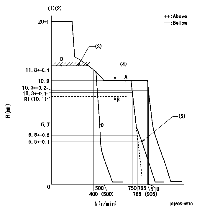
N:Pump speed
R:Rack position (mm)
(1)Target notch: K
(2)Tolerance for racks not indicated: +-0.05mm.
(3)Boost compensator excessive fuel lever at operation (at 0 boost pressure): L1
(4)Boost compensator stroke: BCL
(5)Set idle sub-spring
----------
K=13 L1=12.3+-0.1mm BCL=(0.8)mm
----------
----------
K=13 L1=12.3+-0.1mm BCL=(0.8)mm
----------
Speed control lever angle
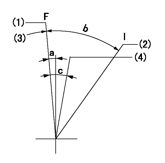
F:Full speed
I:Idle
(1)Set the pump speed at aa
(2)Stopper bolt setting
(3)Stopper bolt setting
(4)When pump speed set at bb
----------
aa=910r/min bb=750r/min
----------
a=5deg+-5deg b=19deg+-5deg c=7deg+-5deg
----------
aa=910r/min bb=750r/min
----------
a=5deg+-5deg b=19deg+-5deg c=7deg+-5deg
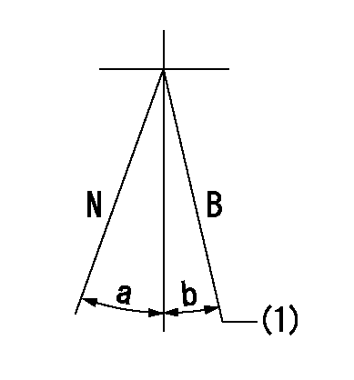
Stop lever angle

N:Pump normal
S:Stop the pump.
----------
----------
a=26deg+-5deg b=53deg+-5deg
----------
----------
a=26deg+-5deg b=53deg+-5deg
0000001101
N:Normal
B:When boosted
(1)Rack position = aa (at boost pressure = bb)
----------
aa=12.3+-0.1mm bb=0kPa(0mmHg)
----------
a=(15deg) b=(7deg)
----------
aa=12.3+-0.1mm bb=0kPa(0mmHg)
----------
a=(15deg) b=(7deg)
0000001501 GOV FULL LOAD ADJUSTMENT
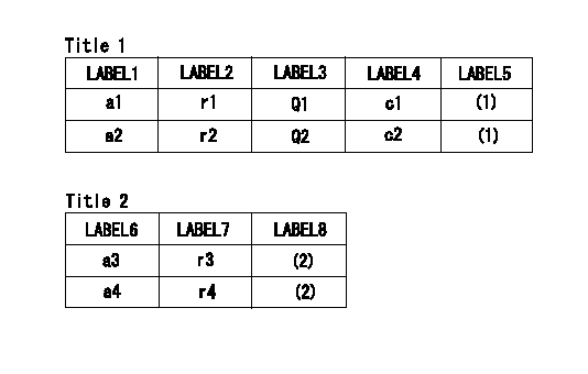
Title1:Full load stopper adjustment
Title2:Governor set speed
LABEL1:Distinguishing
LABEL2:Pump speed (r/min)
LABEL3:Ave. injection quantity (mm3/st)
LABEL4:Max. var. bet. cyl.
LABEL5:Remarks
LABEL6:Distinguishing
LABEL7:Governor set speed (r/min)
LABEL8:Remarks
(1)Adjustment conditions are the same as those for measuring injection quantity.
(2)-
----------
----------
a1=A a2=- r1=700r/min r2=- Q1=105.5+-1.5mm3/st Q2=- c1=+-2.5% c2=- a3=18 a4=15 r3=900r/min r4=750r/min
----------
----------
a1=A a2=- r1=700r/min r2=- Q1=105.5+-1.5mm3/st Q2=- c1=+-2.5% c2=- a3=18 a4=15 r3=900r/min r4=750r/min
Timing setting

(1)Pump vertical direction
(2)Coupling's key groove position at No 1 cylinder's beginning of injection
(3)B.T.D.C.: aa
(4)-
----------
aa=18deg
----------
a=(30deg)
----------
aa=18deg
----------
a=(30deg)
Information:
New Dipsticks With Full Range Readings
The new rear sump and front sump dipsticks are used with their respective oil pans. These oil pans are used in truck applications with set-back axles.The new dipsticks are different because they have a FULL RANGE zone versus other dipsticks that have the traditional FULL mark. These dipsticks are used for truck applications with various angles and slants of engine installation (angle = front to back tilt, slant = sideways tilt).Calibration
Use the following procedure to calibrate FULL RANGE dipsticks. A convenient time to calibrate the dipstick is at the first oil change.Refer to the PM Level 1 of the Maintenance Management Schedule of this publication for the proper oil change interval.To verify the "ADD" mark and establish the actual "FULL" mark, use the following procedure: Truck must be parked on a level surface.1. Operate the engine until it reaches normal operating temperature.2. Stop the engine. Drain the oil and change the oil filter.3. Fill the crankcase with 32 U.S. quarts (30.3 liters) of oil. Brakesaver models require 36 quarts (34 L). Remote mounted or auxiliary filters require additional oil. For all information pertaining to auxiliary oil filters, refer to the OEM or manufacturer's instructions.4. Allow the oil to drain back to the sump for a minimum of five minutes.5. Remove the dipstick. The oil level should be at the ADD mark. If it is not, mark the actual level on the dipstick. This is now the correct ADD mark.6. Add an additional 4 U.S. quarts (3.8 liters) of oil to the sump. Allow enough time for the oil to drain into the sump. Again, check the level on the dipstick.7. This is the correct FULL mark in the FULL RANGE zone on the dipstick. If it is not, mark the new FULL level on the dipstick. Remote mounted or auxiliary filters require additional oil also. For all information pertaining to auxiliary oil filters, refer to the OEM or manufacturer's instructions.8. Start the engine and operate until it reaches normal operating temperature. Stop the engine.9. Allow the oil to drain back to the sump for a minimum of 10 minutes.10. Remove the dipstick. The oil level should be near the FULL mark. If it is not, add oil until the level reaches the FULL mark on the dipstick.This procedure is correct for use with either the non-spacer plate oil pan or the spacer plate oil pan. Sump capacities and oil levels are the same for each oil pan.Any FULL RANGE dipstick for the 3406B Truck engine can be calibrated using this procedure.
Have questions with 101605-9570?
Group cross 101605-9570 ZEXEL
Daewoo
Mitsubishi-Heav
Mitsubishi-Heav
Mitsubishi-Heav
Yanmar
Nissan-Diesel
101605-9570
9 400 610 706
1671295005
INJECTION-PUMP ASSEMBLY
NE6T15
NE6T15