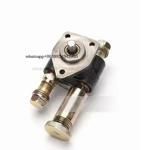
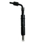
Information injection-pump assembly
BOSCH
9 400 610 705
9400610705
ZEXEL
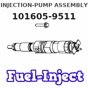
101605-9511
1016059511
MITSUBISHI-HEAV
3436102090
3436102090
Rating:
Compare Prices: .
As an associate, we earn commssions on qualifying purchases through the links below
Fuel Injection Pump 3436102090 ME755056 9410610309 101605-9511 for Mitsubishi Engine S6R S12R S12H S16R S8U S12U
100% Apollo part number:3436102090 ME755056 || application: for Mitsubishi Engine S6R S12R S12H S16R S8U S12U
100% Apollo part number:3436102090 ME755056 || application: for Mitsubishi Engine S6R S12R S12H S16R S8U S12U
Fuel Injection Pump Compatible with 9410610309 ME755056 Mitsubishi 101605-9511 Zexel
Starhycfa Product name:Fuel Injection Pump || Part Number:9410610309 ME755056 || APPlication:Compatible with Mitsubishi 101605-9511 Zexel || 1.Please carefully compare the pictures or OE numbers to match your original parts beCompatible withe purchasing the product. || 2.Please make sure that the model number, part number and photo is the same as yours beCompatible withe order. To Avoid placing wrong orders and wasting your precious time.
Starhycfa Product name:Fuel Injection Pump || Part Number:9410610309 ME755056 || APPlication:Compatible with Mitsubishi 101605-9511 Zexel || 1.Please carefully compare the pictures or OE numbers to match your original parts beCompatible withe purchasing the product. || 2.Please make sure that the model number, part number and photo is the same as yours beCompatible withe order. To Avoid placing wrong orders and wasting your precious time.
Service parts 101605-9511 INJECTION-PUMP ASSEMBLY:
1.
_
5.
AUTOM. ADVANCE MECHANIS
6.
COUPLING PLATE
7.
COUPLING PLATE
8.
_
9.
_
11.
Nozzle and Holder
34361-11010
12.
Open Pre:MPa(Kqf/cm2)
21.6{220}
15.
NOZZLE SET
Include in #1:
101605-9511
as INJECTION-PUMP ASSEMBLY
Include in #2:
104134-1050
as _
Cross reference number
BOSCH
9 400 610 705
9400610705
ZEXEL
101605-9511
1016059511
MITSUBISHI-HEAV
3436102090
3436102090
Zexel num
Bosch num
Firm num
Name
Calibration Data:
Adjustment conditions
Test oil
1404 Test oil ISO4113 or {SAEJ967d}
1404 Test oil ISO4113 or {SAEJ967d}
Test oil temperature
degC
40
40
45
Nozzle and nozzle holder
105780-8140
Bosch type code
EF8511/9A
Nozzle
105780-0000
Bosch type code
DN12SD12T
Nozzle holder
105780-2080
Bosch type code
EF8511/9
Opening pressure
MPa
17.2
Opening pressure
kgf/cm2
175
Injection pipe
Outer diameter - inner diameter - length (mm) mm 6-2-600
Outer diameter - inner diameter - length (mm) mm 6-2-600
Overflow valve
131424-5720
Overflow valve opening pressure
kPa
255
221
289
Overflow valve opening pressure
kgf/cm2
2.6
2.25
2.95
Tester oil delivery pressure
kPa
157
157
157
Tester oil delivery pressure
kgf/cm2
1.6
1.6
1.6
Direction of rotation (viewed from drive side)
Right R
Right R
Injection timing adjustment
Direction of rotation (viewed from drive side)
Right R
Right R
Injection order
1-5-3-6-
2-4
Pre-stroke
mm
3.2
3.15
3.25
Beginning of injection position
Drive side NO.1
Drive side NO.1
Difference between angles 1
Cal 1-5 deg. 60 59.5 60.5
Cal 1-5 deg. 60 59.5 60.5
Difference between angles 2
Cal 1-3 deg. 120 119.5 120.5
Cal 1-3 deg. 120 119.5 120.5
Difference between angles 3
Cal 1-6 deg. 180 179.5 180.5
Cal 1-6 deg. 180 179.5 180.5
Difference between angles 4
Cyl.1-2 deg. 240 239.5 240.5
Cyl.1-2 deg. 240 239.5 240.5
Difference between angles 5
Cal 1-4 deg. 300 299.5 300.5
Cal 1-4 deg. 300 299.5 300.5
Injection quantity adjustment
Adjusting point
A
Rack position
9.8
Pump speed
r/min
900
900
900
Average injection quantity
mm3/st.
93
92
94
Max. variation between cylinders
%
0
-2.5
2.5
Basic
*
Fixing the lever
*
Injection quantity adjustment_02
Adjusting point
C
Rack position
5.7+-0.5
Pump speed
r/min
450
450
450
Average injection quantity
mm3/st.
11
9.7
12.3
Max. variation between cylinders
%
0
-14
14
Fixing the rack
*
Injection quantity adjustment_03
Adjusting point
D
Rack position
-
Pump speed
r/min
100
100
100
Average injection quantity
mm3/st.
90
90
95
Fixing the lever
*
Rack limit
*
Test data Ex:
Governor adjustment
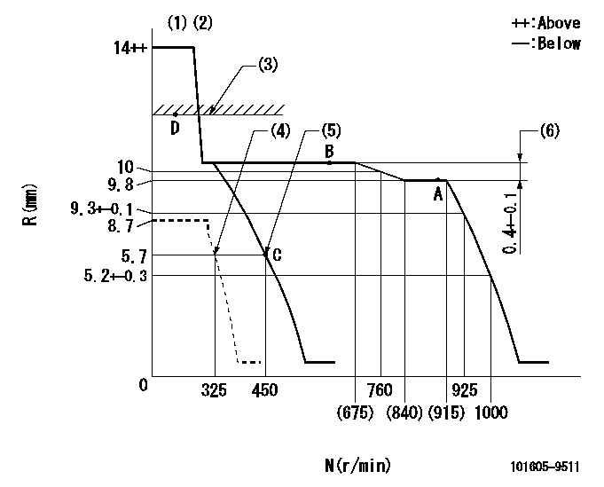
N:Pump speed
R:Rack position (mm)
(1)Target notch: K
(2)Tolerance for racks not indicated: +-0.05mm.
(3)RACK LIMIT
(4)Set idle sub-spring
(5)Main spring setting
(6)Rack difference between N = N1 and N = N2
----------
K=13 N1=900r/min N2=650r/min
----------
----------
K=13 N1=900r/min N2=650r/min
----------
Speed control lever angle
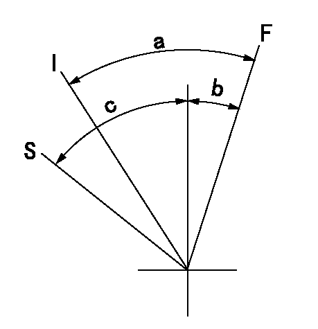
F:Full speed
I:Idle
S:Stop
----------
----------
a=19deg+-5deg b=3deg+-5deg c=35deg+-3deg
----------
----------
a=19deg+-5deg b=3deg+-5deg c=35deg+-3deg
Stop lever angle
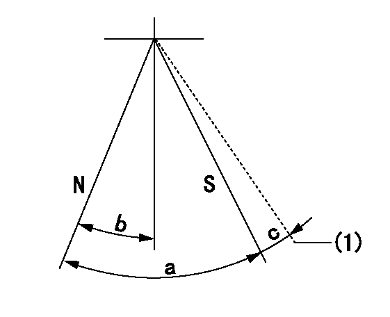
N:Pump normal
S:Stop the pump.
(1)Hold the boss against the stop side
----------
----------
a=53deg+-5deg b=26.5deg+-5deg c=(9deg)
----------
----------
a=53deg+-5deg b=26.5deg+-5deg c=(9deg)
Timing setting

(1)Pump vertical direction
(2)Position of camshaft's key groove at No 1 cylinder's beginning of injection
(3)-
(4)-
----------
----------
a=(50deg)
----------
----------
a=(50deg)
Information:
Adjust Alternator Belts
3. Loosen the mounting pivot bolt (1). Loosen the adjustment nut(s) (2).4. Adjust the alternator in or out by either tightening or loosening adjustment nut(s) as required to obtain the correct adjustment.5. Tighten bolts (1) and (2). Check the belt tension. Install the belt guard.If new belts are installed, check belt adjustment again after 30 minutes of engine operation. Repeat belt tightening if required.Adjust Fan Drive Belts
1. Loosen bolts holding the fan mounting plate to the engine.2. Loosen locknut and turn adjusting screw until the belts are properly adjusted.3. Tighten bolts and locknut.4. Check the belt adjustment. If adjustment is not correct, repeat steps 1 through 3.Inspect/Replace Hoses and Clamps
Hose replacement prior to failure is a good preventive maintenance practice. Replacing a hose before it fails reduces the chances for unscheduled downtime. By replacing a hose that is cracked, soft or leaking, major repairs will be avoided that could result in a severe engine overheating problem.* Inspect all hoses for leaks due to cracking, softness and loose clamps.* Replace hoses that are cracked or soft and tighten loose clamps.Before Replacing Hoses
1. Loosen the cooling system filler cap slowly to relieve any pressure and remove the cap.2. Drain the coolant from the cooling system to a level below the hose being replaced. Remove the hose clamps, disconnect the old hose and replace with a new hose. Install hose clamps. See the Torque for Standard Hose Clamps chart in the Torque Specifications section of this publication for the appropriate torque.After Replacing Hoses
Refer to the Cooling System Specifications section in this publication for information about cooling system requirements.3. Add proper coolant mixture to the cooling system. Fill system to the proper level. Install the filler cap. Start the engine and inspect for cooling system leaks.4. Check coolant temperature reading frequently for proper operating temperature.Engine Air Cleaner
Never service the air cleaner with the engine running since this will allow dirt to enter the engine. Check the inlet piping for leaks. Make all repairs to inlet piping immediately, as dirt and debris could enter the engine causing damage to the turbocharger and engine components.Clean or replace elements using these recommendations and/or your weather and operating conditions, or when required by the restriction indicator.
Replace
Regular service intervals, along with close visual inspection of the air cleaners are necessary for proper cleaning of the engine inlet air. The interval will vary with the weather and operating conditions. It will be necessary to service the air cleaners more frequently in salty, dry weather conditions or where airborne dust and debris is present. In damp weather conditions the service interval may be extended, however the elements should be replaced EVERY YEAR.Visual inspection of the gaskets and seals is important to keep dust from bypassing the cleaner elements. If the gaskets and seals or the element pleats are damaged, replace them. Extra filter elements should be kept on hand for replacement or for use while elements are being cleaned. Refer to topic Air Cleaner Indicator in the


