Information injection-pump assembly
BOSCH
9 400 615 383
9400615383
ZEXEL
101605-9500
1016059500
Rating:
Cross reference number
BOSCH
9 400 615 383
9400615383
ZEXEL
101605-9500
1016059500
Zexel num
Bosch num
Firm num
Name
9 400 615 383
DAEWOO
INJECTION-PUMP ASSEMBLY
DB58NA K 14BE INJECTION PUMP ASSY PE6A PE
DB58NA K 14BE INJECTION PUMP ASSY PE6A PE
Calibration Data:
Adjustment conditions
Test oil
1404 Test oil ISO4113 or {SAEJ967d}
1404 Test oil ISO4113 or {SAEJ967d}
Test oil temperature
degC
40
40
45
Nozzle and nozzle holder
105780-8140
Bosch type code
EF8511/9A
Nozzle
105780-0000
Bosch type code
DN12SD12T
Nozzle holder
105780-2080
Bosch type code
EF8511/9
Opening pressure
MPa
17.2
Opening pressure
kgf/cm2
175
Injection pipe
Outer diameter - inner diameter - length (mm) mm 6-2-600
Outer diameter - inner diameter - length (mm) mm 6-2-600
Tester oil delivery pressure
kPa
157
157
157
Tester oil delivery pressure
kgf/cm2
1.6
1.6
1.6
Direction of rotation (viewed from drive side)
Right R
Right R
Injection timing adjustment
Direction of rotation (viewed from drive side)
Right R
Right R
Injection order
1-5-3-6-
2-4
Pre-stroke
mm
3.6
3.55
3.65
Beginning of injection position
Drive side NO.1
Drive side NO.1
Difference between angles 1
Cal 1-5 deg. 60 59.5 60.5
Cal 1-5 deg. 60 59.5 60.5
Difference between angles 2
Cal 1-3 deg. 120 119.5 120.5
Cal 1-3 deg. 120 119.5 120.5
Difference between angles 3
Cal 1-6 deg. 180 179.5 180.5
Cal 1-6 deg. 180 179.5 180.5
Difference between angles 4
Cyl.1-2 deg. 240 239.5 240.5
Cyl.1-2 deg. 240 239.5 240.5
Difference between angles 5
Cal 1-4 deg. 300 299.5 300.5
Cal 1-4 deg. 300 299.5 300.5
Injection quantity adjustment
Adjusting point
A
Rack position
9.1
Pump speed
r/min
800
800
800
Average injection quantity
mm3/st.
56
55
57
Max. variation between cylinders
%
0
-2
2
Basic
*
Fixing the lever
*
Injection quantity adjustment_02
Adjusting point
C
Rack position
6.4+-0.5
Pump speed
r/min
415
415
415
Average injection quantity
mm3/st.
6
4.7
7.3
Fixing the rack
*
Injection quantity adjustment_03
Adjusting point
D
Rack position
-
Pump speed
r/min
100
100
100
Average injection quantity
mm3/st.
100
90
110
Fixing the lever
*
Rack limit
*
Injection quantity adjustment_04
Adjusting point
E
Rack position
6.7+-0.5
Pump speed
r/min
415
415
415
Average injection quantity
mm3/st.
8
6.7
9.3
Max. variation between cylinders
%
0
-14
14
Fixing the rack
*
Test data Ex:
Governor adjustment
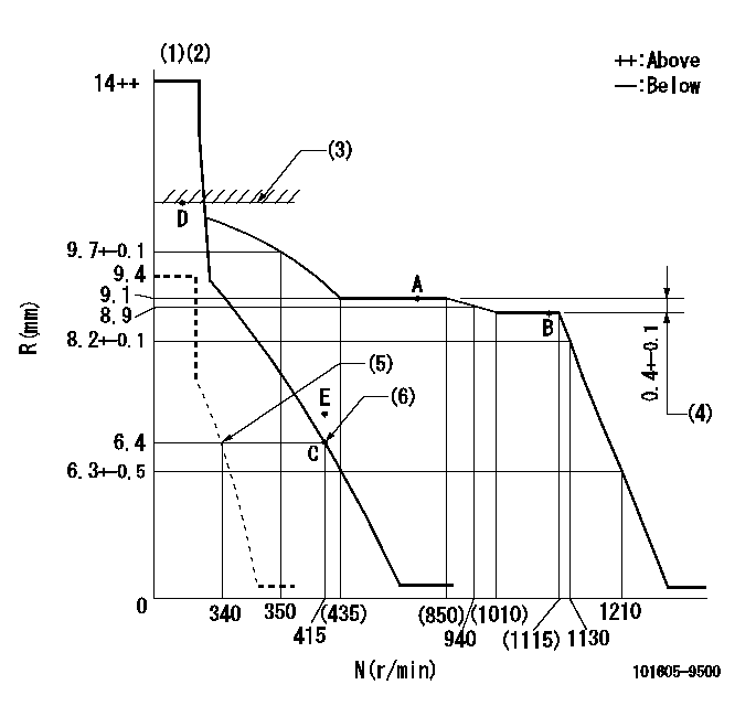
N:Pump speed
R:Rack position (mm)
(1)Target notch: K
(2)Tolerance for racks not indicated: +-0.05mm.
(3)RACK LIMIT
(4)Rack difference between N = N1 and N = N2
(5)Set idle sub-spring
(6)Main spring setting
----------
K=13 N1=1100r/min N2=800r/min
----------
----------
K=13 N1=1100r/min N2=800r/min
----------
Speed control lever angle
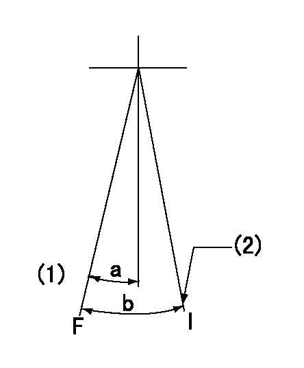
F:Full speed
I:Idle
(1)-
(2)Stopper bolt setting
----------
----------
a=10deg+-5deg b=19deg+-5deg
----------
----------
a=10deg+-5deg b=19deg+-5deg
Stop lever angle

N:Pump normal
S:Stop the pump.
----------
----------
a=19deg+-5deg b=53deg+-5deg
----------
----------
a=19deg+-5deg b=53deg+-5deg
Timing setting

(1)Pump vertical direction
(2)Position of gear mark 'CC' at No 1 cylinder's beginning of injection
(3)B.T.D.C.: aa
(4)-
----------
aa=20deg
----------
a=(90deg)
----------
aa=20deg
----------
a=(90deg)
Information:
2. Maintain the oil level to the FULL mark (between the ADD and FULL RANGE zone) on the ENGINE STOPPED WITH OIL COLD side of the dipstick. Do not fill the crankcase above the FULL RANGE zone.3. Remove oil fill cap and add oil if necessary. DO NOT fill the crankcase above the FULL mark on the dipstick.
Do NOT overfill to reach above or to the top of the FULL mark on the dipstick.
Operating your engine when the oil level is above the FULL Range zone could cause your crankshaft to dip into the oil. If this occurs during engine operation, it could result in a loss of power and a possible alarm from high crankcase pressure. Remote mounted or auxiliary filters require additional oil. For all information pertaining to auxiliary filters, refer to the OEM or filter manufacturer's recommendations and instructions for all information regarding auxiliary oil filters.Estimating Oil Consumption
Oil consumption, along with fuel consumption and maintenance information, can be used to estimate total operating cost for your Caterpillar engine. It can also be used to estimate the capacity of a makeup oil system required to accommodate your maintenance intervals.Oil consumption is somewhat proportional to the percent load at which the engine is operating. The higher the percent load, the higher the amount of oil consumed per hour.The oil consumption rate, or BSOC (brake specific oil consumption), measure is grams/brake kW-hour (lb/bhp-hour). The BSOC varies depending on the load on your engine. The established typical mid-life BSOC values for your engine can be determined by contacting your Caterpillar dealer for assistance in determining typical oil consumption for your engine.Oil Consumption as an Overhaul Indicator
When an engine's oil consumption has risen to three times the initial (new) consumption rate due to normal wear, then the engine should be scheduled for overhaul. There may be a corresponding increase in blowby and also a slight increase in fuel consumption. Contact your Caterpillar dealer for assistance in determining typical oil consumption for your engine.Cooling System
Make sure you read and understand the information in the Safety and Cooling System Specifications sections of this manual before you proceed with maintenance of the cooling system.
Check Coolant Level
If Coolant is Low
Refer to the Cooling System Specifications section in this publication for all information pertaining to water, antifreeze and supplemental coolant additive requirements before performing this maintenance procedure.1. Stop the engine and allow the engine to cool before performing this maintenance procedure.2. Release vent valve (if equipped) slowly to relieve pressure. Remove filler cap and inspect condition of cap gasket. Replace cap if gaskets are damaged.3. Maintain the coolant level within 13 mm (1/2 inch) below the bottom of the fill pipe or to the proper level (upper half) on the sight glass (if equipped) by adding make-up coolant (antifreeze and water). Install the filler cap.4. Inspect for leaks or damaged piping. Make repairs if necessary.Air Cleaner Indicator
Typical air cleaner indicator shown.Check the service indicator (if equipped) mounted on the air cleaner. A colored piston showing