Information injection-pump assembly
BOSCH
9 400 610 703
9400610703
ZEXEL
101605-9460
1016059460
NISSAN-DIESEL
16712Z5511
16712z5511
Rating:
Service parts 101605-9460 INJECTION-PUMP ASSEMBLY:
1.
_
5.
AUTOM. ADVANCE MECHANIS
7.
COUPLING PLATE
8.
_
9.
_
11.
Nozzle and Holder
16600-Z5607
12.
Open Pre:MPa(Kqf/cm2)
19.6{200}
15.
NOZZLE SET
Cross reference number
BOSCH
9 400 610 703
9400610703
ZEXEL
101605-9460
1016059460
NISSAN-DIESEL
16712Z5511
16712z5511
Zexel num
Bosch num
Firm num
Name
101605-9460
9 400 610 703
16712Z5511 NISSAN-DIESEL
INJECTION-PUMP ASSEMBLY
FE6T45 K 14BE INJECTION PUMP ASSY PE6A PE
FE6T45 K 14BE INJECTION PUMP ASSY PE6A PE
Calibration Data:
Adjustment conditions
Test oil
1404 Test oil ISO4113 or {SAEJ967d}
1404 Test oil ISO4113 or {SAEJ967d}
Test oil temperature
degC
40
40
45
Nozzle and nozzle holder
105780-8140
Bosch type code
EF8511/9A
Nozzle
105780-0000
Bosch type code
DN12SD12T
Nozzle holder
105780-2080
Bosch type code
EF8511/9
Opening pressure
MPa
17.2
Opening pressure
kgf/cm2
175
Injection pipe
Outer diameter - inner diameter - length (mm) mm 6-2-600
Outer diameter - inner diameter - length (mm) mm 6-2-600
Overflow valve
131424-1520
Overflow valve opening pressure
kPa
157
123
191
Overflow valve opening pressure
kgf/cm2
1.6
1.25
1.95
Tester oil delivery pressure
kPa
157
157
157
Tester oil delivery pressure
kgf/cm2
1.6
1.6
1.6
Direction of rotation (viewed from drive side)
Right R
Right R
Injection timing adjustment
Direction of rotation (viewed from drive side)
Right R
Right R
Injection order
1-4-2-6-
3-5
Pre-stroke
mm
3.3
3.25
3.35
Beginning of injection position
Drive side NO.1
Drive side NO.1
Difference between angles 1
Cal 1-4 deg. 60 59.5 60.5
Cal 1-4 deg. 60 59.5 60.5
Difference between angles 2
Cyl.1-2 deg. 120 119.5 120.5
Cyl.1-2 deg. 120 119.5 120.5
Difference between angles 3
Cal 1-6 deg. 180 179.5 180.5
Cal 1-6 deg. 180 179.5 180.5
Difference between angles 4
Cal 1-3 deg. 240 239.5 240.5
Cal 1-3 deg. 240 239.5 240.5
Difference between angles 5
Cal 1-5 deg. 300 299.5 300.5
Cal 1-5 deg. 300 299.5 300.5
Injection quantity adjustment
Adjusting point
A
Rack position
8.5
Pump speed
r/min
750
750
750
Average injection quantity
mm3/st.
69.5
67.5
71.5
Max. variation between cylinders
%
0
-3.5
3.5
Basic
*
Fixing the rack
*
Boost pressure
kPa
42
42
Boost pressure
mmHg
315
315
Injection quantity adjustment_02
Adjusting point
C
Rack position
R1(8.6)
Pump speed
r/min
400
400
400
Average injection quantity
mm3/st.
53
52
54
Max. variation between cylinders
%
0
-5
5
Fixing the lever
*
Boost pressure
kPa
0
0
0
Boost pressure
mmHg
0
0
0
Injection quantity adjustment_03
Adjusting point
D
Rack position
6.8+-0.5
Pump speed
r/min
350
350
350
Average injection quantity
mm3/st.
8
6.2
9.8
Max. variation between cylinders
%
0
-10
10
Fixing the rack
*
Boost pressure
kPa
0
0
0
Boost pressure
mmHg
0
0
0
Boost compensator adjustment
Pump speed
r/min
400
400
400
Rack position
R1(8.6)
Boost pressure
kPa
4.7
3.4
6
Boost pressure
mmHg
35
25
45
Boost compensator adjustment_02
Pump speed
r/min
400
400
400
Rack position
(9.5)
Boost pressure
kPa
28.7
28.7
28.7
Boost pressure
mmHg
215
215
215
Test data Ex:
Governor adjustment
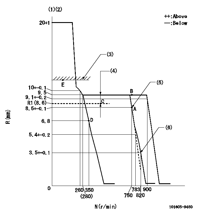
N:Pump speed
R:Rack position (mm)
(1)Target notch: K
(2)Tolerance for racks not indicated: +-0.05mm.
(3)Boost compensator excessive fuel lever at operation (at 0 boost pressure): L1
(4)Boost compensator stroke: BCL
(5)Main spring setting
(6)Set idle sub-spring
----------
K=13 L1=10.5+-0.1mm BCL=(0.9)mm
----------
----------
K=13 L1=10.5+-0.1mm BCL=(0.9)mm
----------
Speed control lever angle
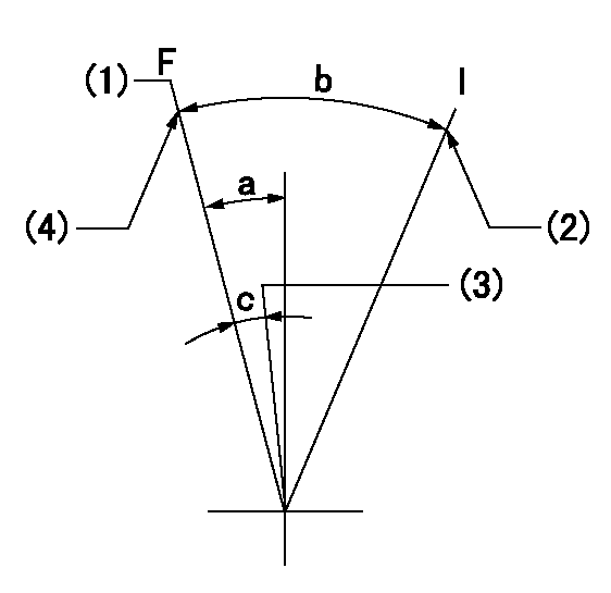
F:Full speed
I:Idle
(1)Set the pump speed at aa
(2)Stopper bolt setting
(3)When pump speed set at bb
(4)Stopper bolt setting
----------
aa=900r/min bb=750r/min
----------
a=6deg+-5deg b=20deg+-5deg c=5deg+-5deg
----------
aa=900r/min bb=750r/min
----------
a=6deg+-5deg b=20deg+-5deg c=5deg+-5deg
Stop lever angle

N:Pump normal
S:Stop the pump.
----------
----------
a=26.5deg+-5deg b=53deg+-5deg
----------
----------
a=26.5deg+-5deg b=53deg+-5deg
0000001101
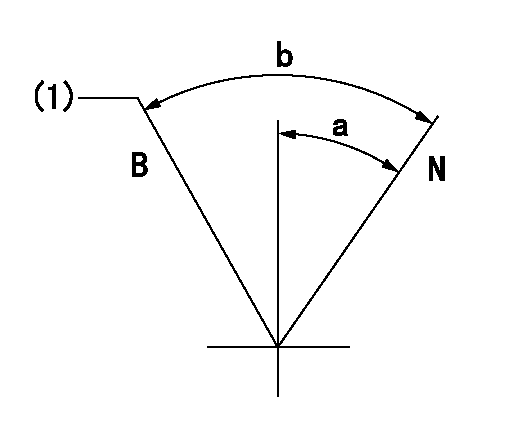
N:Normal
B:When boosted
(1)Rack position = aa (at boost pressure = bb)
----------
aa=10.5+-0.1mm bb=0kPa(0mmHg)
----------
a=(15deg) b=(25deg)
----------
aa=10.5+-0.1mm bb=0kPa(0mmHg)
----------
a=(15deg) b=(25deg)
Timing setting

(1)Pump vertical direction
(2)Position of coupling's threaded hole at No 1 cylinder's beginning of injection
(3)-
(4)-
----------
----------
a=(60deg)
----------
----------
a=(60deg)
Information:
Stopping the engine immediately after it has been working under load can result in overheating and accelerated wear of the engine components. Excessive temperatures in the turbocharger centerhousing will cause oil coking problems.
Prior to stopping an engine that is being operated at low loads, run the engine at low speed for 30 seconds before stopping. If the engine has been operating at high load, then it should be run at low speed for three to five minutes to reduce and stabilize internal engine coolant and oil temperatures before stopping. Avoiding hot engine shutdowns will maximize turbocharger shaft and bearing life. Make sure the Engine Stopping procedure is understood.Follow the engine stopping procedure outlined below to allow the engine to cool. Make sure the Engine Stopping procedure is understood.The engine may be shutdown in several ways. To manually stop the engine, refer to the following information and instructions. The engine is equipped with an Emergency Stop Push Button (ESPB) and an Engine Control Switch (ECS), which is OEM provided.Emergency Stop Procedure
Emergency stop controls are for EMERGENCY use ONLY. DO NOT use Emergency Stop Pushbutton (ESPB) for normal stopping procedure. Do NOT start the engine until the problem necessitating the emergency stop has been located and corrected.
The engine may be installed with an Emergency Stop Pushbutton. The Emergency Stop Pushbutton may be located on the front of the control panel. The Emergency Stop Pushbutton will cause immediate shutoff of fuel and/or air. Emergency shutoff controls (including any auxiliary Emergency Stop inputs) should only be used when an emergency exists, and not used to routinely stop the engine.* Emergency stops may be made through the Emergency Stop Pushbutton (ESPB). If the need for emergency engine shutdown occurs, Push the EMERGENCY STOP Pushbutton located on the control panel. This will activate the air and/or fuel shutoffs.* Reset the EMERGENCY STOP Pushbutton (pull out and rotate the button in the direction indicated on the button). Some EMERGENCY STOP Pushbuttons can be pulled out to reset, not requiring any rotation.Manual Fuel Shutoff
A manual shutdown shaft is provided to override the governor control of the engine. This shutdown will only move the fuel control linkage to the fuel OFF position to starve the engine of fuel. The engine will coast to a stop. Be sure to secure any external system components that have been operating to support the engine operation.Manual Stop Procedure
Follow the engine stopping procedure outlined below, to allow the engine to cool. Make sure the Engine Stopping procedure is clearly understood.1. Reduce engine speed to low idle.2. Disengage driven equipment or remove load from engine.3. Move governor control to increase engine speed to no more than half engine speed for two minutes.4. Reduce engine speed to low idle for five minutes to cool the engine and prevent oil coking problems in the turbocharger centerhousing.5. Depending on your control, stop the engine by turning the start switch to the OFF position or refer below to the governor controls that your engine may be equipped
Have questions with 101605-9460?
Group cross 101605-9460 ZEXEL
Mitsubishi-Heav
Dpico
Mitsubishi-Heav
Nissan-Diesel
Nissan-Diesel
101605-9460
9 400 610 703
16712Z5511
INJECTION-PUMP ASSEMBLY
FE6T45
FE6T45