Information injection-pump assembly
ZEXEL
101605-9451
1016059451

Rating:
Service parts 101605-9451 INJECTION-PUMP ASSEMBLY:
1.
_
5.
AUTOM. ADVANCE MECHANIS
7.
COUPLING PLATE
8.
_
9.
_
11.
Nozzle and Holder
16600-Z5607
12.
Open Pre:MPa(Kqf/cm2)
19.6{200}
15.
NOZZLE SET
Cross reference number
ZEXEL
101605-9451
1016059451
Zexel num
Bosch num
Firm num
Name
101605-9451
INJECTION-PUMP ASSEMBLY
Calibration Data:
Adjustment conditions
Test oil
1404 Test oil ISO4113 or {SAEJ967d}
1404 Test oil ISO4113 or {SAEJ967d}
Test oil temperature
degC
40
40
45
Nozzle and nozzle holder
105780-8140
Bosch type code
EF8511/9A
Nozzle
105780-0000
Bosch type code
DN12SD12T
Nozzle holder
105780-2080
Bosch type code
EF8511/9
Opening pressure
MPa
17.2
Opening pressure
kgf/cm2
175
Injection pipe
Outer diameter - inner diameter - length (mm) mm 6-2-600
Outer diameter - inner diameter - length (mm) mm 6-2-600
Overflow valve
131424-1520
Overflow valve opening pressure
kPa
157
123
191
Overflow valve opening pressure
kgf/cm2
1.6
1.25
1.95
Tester oil delivery pressure
kPa
157
157
157
Tester oil delivery pressure
kgf/cm2
1.6
1.6
1.6
Direction of rotation (viewed from drive side)
Right R
Right R
Injection timing adjustment
Direction of rotation (viewed from drive side)
Right R
Right R
Injection order
1-4-2-6-
3-5
Pre-stroke
mm
3.3
3.25
3.35
Beginning of injection position
Drive side NO.1
Drive side NO.1
Difference between angles 1
Cal 1-4 deg. 60 59.5 60.5
Cal 1-4 deg. 60 59.5 60.5
Difference between angles 2
Cyl.1-2 deg. 120 119.5 120.5
Cyl.1-2 deg. 120 119.5 120.5
Difference between angles 3
Cal 1-6 deg. 180 179.5 180.5
Cal 1-6 deg. 180 179.5 180.5
Difference between angles 4
Cal 1-3 deg. 240 239.5 240.5
Cal 1-3 deg. 240 239.5 240.5
Difference between angles 5
Cal 1-5 deg. 300 299.5 300.5
Cal 1-5 deg. 300 299.5 300.5
Injection quantity adjustment
Adjusting point
A
Rack position
10
Pump speed
r/min
800
800
800
Average injection quantity
mm3/st.
91.5
89.5
93.5
Max. variation between cylinders
%
0
-3.5
3.5
Basic
*
Fixing the lever
*
Boost pressure
kPa
33.3
33.3
Boost pressure
mmHg
250
250
Injection quantity adjustment_02
Adjusting point
B
Rack position
R1(9.9)
Pump speed
r/min
400
400
400
Average injection quantity
mm3/st.
72
71
73
Max. variation between cylinders
%
0
-5
5
Fixing the lever
*
Boost pressure
kPa
0
0
0
Boost pressure
mmHg
0
0
0
Injection quantity adjustment_03
Adjusting point
C
Rack position
6.9+-0.5
Pump speed
r/min
350
350
350
Average injection quantity
mm3/st.
9
7.2
10.8
Max. variation between cylinders
%
0
-10
10
Fixing the rack
*
Boost pressure
kPa
0
0
0
Boost pressure
mmHg
0
0
0
Boost compensator adjustment
Pump speed
r/min
400
400
400
Rack position
R1(9.9)
Boost pressure
kPa
6.7
4
9.4
Boost pressure
mmHg
50
30
70
Boost compensator adjustment_02
Pump speed
r/min
400
400
400
Rack position
(10)
Boost pressure
kPa
20
20
20
Boost pressure
mmHg
150
150
150
Test data Ex:
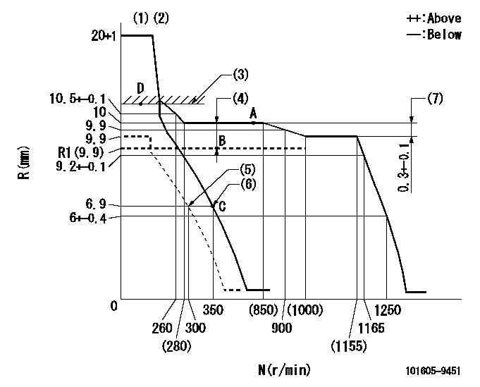
Governor adjustment

N:Pump speed
R:Rack position (mm)
(1)Target notch: K
(2)Tolerance for racks not indicated: +-0.05mm.
(3)Boost compensator excessive fuel lever at operation: L1 (at 0 boost pressure)
(4)Boost compensator stroke: BCL
(5)Set idle sub-spring
(6)Main spring setting
(7)Rack difference between N = N1 and N = N2
----------
K=10 L1=11.9+-0.1mm BCL=(0.1)mm N1=1100r/min N2=800r/min
----------
----------
K=10 L1=11.9+-0.1mm BCL=(0.1)mm N1=1100r/min N2=800r/min
----------
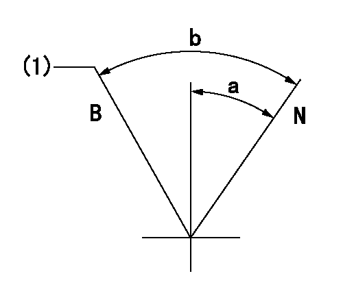
Speed control lever angle

F:Full speed
I:Idle
(1)Stopper bolt setting
----------
----------
a=(15deg)+-5deg b=(23deg)+-5deg
----------
----------
a=(15deg)+-5deg b=(23deg)+-5deg
Stop lever angle

N:Pump normal
S:Stop the pump.
----------
----------
a=26.5deg+-5deg b=53deg+-5deg
----------
----------
a=26.5deg+-5deg b=53deg+-5deg
0000001101

N:Normal
B:When boosted
(1)Rack position = aa at boost pressure 0.
----------
aa=11.9+-0.1mm
----------
a=(15deg) b=(25deg)
----------
aa=11.9+-0.1mm
----------
a=(15deg) b=(25deg)
Timing setting

(1)Pump vertical direction
(2)Position of coupling's threaded hole at No 1 cylinder's beginning of injection
(3)-
(4)-
----------
----------
a=(60deg)
----------
----------
a=(60deg)
Information:
Engine Oil Pressure
The sensor utilizes engine oil pressure and engine speed to perform low engine oil pressure detection for diagnostic and annunciation.The graph below illustrates the limits of low engine oil pressure diagnostic and annunciation. The output from the ECM can be used to drive a relay or a lamp to annunciate Low Oil Pressure conditions.
Oil Pressure ParametersLow Oil Pressure Alarm
Oil pressure sensor location.The sensor is mounted in the front of the engine cylinder block with oil lines connected to the switch. Low engine oil pressure closes the switch.The oil pressure switch senses oil pressure at the bearing oil gallery. No resetting procedure is required. Switches may close at 48 to 62 kPa (7 to 9 psi) below actual trip point.Oil Pressure Sensor Failure
When the sensor output is open, shorted to ground or supply, or measured oil pressure reading is out of specification, a sensor failure may have occurred.The ECM will detect the oil pressure sensor failure and through the diagnostic lamp warn the user about the oil pressure sensor failure. The oil pressure related strategies will be disabled. The oil pressure sensor failure will not cause an engine shut down, power derating, or any engine speed change.Speed Sensing Loss Alarm
When the engine speed sensor can no longer sense engine speed, an alarm and diagnostic code entry will occur. If the ECM can not detect any engine speed, the engine will shut down.Manual Fuel Shutoff Lever
Do not use the emergency shutoff control for a normal stopping procedure.
Manual shutdown shaft with lever location.A manual shutdown shaft is provided to override the governor solenoid. This shutdown will only move the fuel control linkage to the fuel OFF position to starve the engine of fuel. It does not shut off the air inlet.Engine Shutoff Controls
Secondary shutoff controls may be electrically, mechanically or hydraulically operated. Familiarize yourself with the types and locations of the shutoff controls, the conditions which cause each control to function, and the resetting procedure required to start your engine.The shutoff controls should be tested every 1000 hours by authorized Caterpillar dealer personnel.Always determine the cause of the shutdown, and have the necessary repairs made before restarting the engine.Shutoff Solenoid Failure
When the shutoff solenoid output is open or shorted to ground or supply, a failure may have occurred.The ECM will detect open or short condition of the shutoff solenoid. If the solenoid is failed "open", the engine will shut down.The shutoff solenoid failure will cause the engine to shut down, but the pilot or service personnel can mechanically reposition the shutoff solenoid and restart the engine.Cold Start Strategy
This feature utilizes the coolant temperature sensor input to improve low temperature engine starting and warm-up. It provides quicker cold starts, smoke cleanup, reduces battery "deep" cycling and extends engine life. The engine timing is fixed at 19.5 degrees. Engine block heaters are provided to maintain minimum engine temperature when the engine is not running.When the coolant temperature is below 60°C (140°F), the cold start strategy is activated using the following parameters
Have questions with 101605-9451?
Group cross 101605-9451 ZEXEL
101605-9451
INJECTION-PUMP ASSEMBLY
