Information injection-pump assembly
ZEXEL
101605-9270
1016059270

Rating:
Cross reference number
ZEXEL
101605-9270
1016059270
Zexel num
Bosch num
Firm num
Name
101605-9270
INJECTION-PUMP ASSEMBLY
Calibration Data:
Adjustment conditions
Test oil
1404 Test oil ISO4113 or {SAEJ967d}
1404 Test oil ISO4113 or {SAEJ967d}
Test oil temperature
degC
40
40
45
Nozzle and nozzle holder
105780-8140
Bosch type code
EF8511/9A
Nozzle
105780-0000
Bosch type code
DN12SD12T
Nozzle holder
105780-2080
Bosch type code
EF8511/9
Opening pressure
MPa
17.2
Opening pressure
kgf/cm2
175
Injection pipe
Outer diameter - inner diameter - length (mm) mm 6-2-600
Outer diameter - inner diameter - length (mm) mm 6-2-600
Overflow valve
131424-1520
Overflow valve opening pressure
kPa
157
123
191
Overflow valve opening pressure
kgf/cm2
1.6
1.25
1.95
Tester oil delivery pressure
kPa
157
157
157
Tester oil delivery pressure
kgf/cm2
1.6
1.6
1.6
Direction of rotation (viewed from drive side)
Right R
Right R
Injection timing adjustment
Direction of rotation (viewed from drive side)
Right R
Right R
Injection order
1-4-2-6-
3-5
Pre-stroke
mm
3.3
3.25
3.35
Beginning of injection position
Drive side NO.1
Drive side NO.1
Difference between angles 1
Cal 1-4 deg. 60 59.5 60.5
Cal 1-4 deg. 60 59.5 60.5
Difference between angles 2
Cyl.1-2 deg. 120 119.5 120.5
Cyl.1-2 deg. 120 119.5 120.5
Difference between angles 3
Cal 1-6 deg. 180 179.5 180.5
Cal 1-6 deg. 180 179.5 180.5
Difference between angles 4
Cal 1-3 deg. 240 239.5 240.5
Cal 1-3 deg. 240 239.5 240.5
Difference between angles 5
Cal 1-5 deg. 300 299.5 300.5
Cal 1-5 deg. 300 299.5 300.5
Injection quantity adjustment
Adjusting point
A
Rack position
10
Pump speed
r/min
1100
1100
1100
Average injection quantity
mm3/st.
95.5
93.5
97.5
Max. variation between cylinders
%
0
-3.5
3.5
Basic
*
Fixing the lever
*
Boost pressure
kPa
60
60
Boost pressure
mmHg
450
450
Injection quantity adjustment_02
Adjusting point
B
Rack position
R1(9.4)
Pump speed
r/min
400
400
400
Average injection quantity
mm3/st.
61
60
62
Max. variation between cylinders
%
0
-5
5
Fixing the lever
*
Boost pressure
kPa
0
0
0
Boost pressure
mmHg
0
0
0
Injection quantity adjustment_03
Adjusting point
C
Rack position
6.9+-0.5
Pump speed
r/min
350
350
350
Average injection quantity
mm3/st.
9
7.2
10.8
Max. variation between cylinders
%
0
-10
10
Fixing the rack
*
Boost pressure
kPa
0
0
0
Boost pressure
mmHg
0
0
0
Boost compensator adjustment
Pump speed
r/min
400
400
400
Rack position
R1(9.4)
Boost pressure
kPa
6.7
1.4
12
Boost pressure
mmHg
50
10
90
Boost compensator adjustment_02
Pump speed
r/min
400
400
400
Rack position
R1+0.5
Boost pressure
kPa
29.3
26.6
32
Boost pressure
mmHg
220
200
240
Boost compensator adjustment_03
Pump speed
r/min
400
400
400
Rack position
(10)
Boost pressure
kPa
46.7
46.7
46.7
Boost pressure
mmHg
350
350
350
Test data Ex:
Governor adjustment

N:Pump speed
R:Rack position (mm)
(1)Target notch: K
(2)Tolerance for racks not indicated: +-0.05mm.
(3)Boost compensator excessive fuel lever at operation: L1 (at 0 boost pressure)
(4)Boost compensator stroke: BCL
(5)Set idle sub-spring
(6)Main spring setting
----------
K=12 L1=11.9+-0.1mm BCL=(0.6)mm
----------
----------
K=12 L1=11.9+-0.1mm BCL=(0.6)mm
----------
Speed control lever angle

F:Full speed
I:Idle
(1)Stopper bolt setting
----------
----------
a=9deg+-5deg b=23deg+-5deg
----------
----------
a=9deg+-5deg b=23deg+-5deg
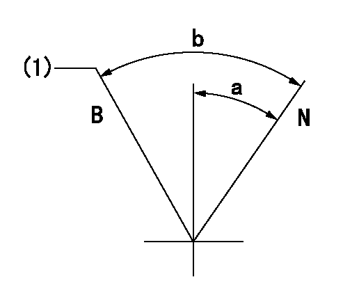
Stop lever angle

N:Pump normal
S:Stop the pump.
----------
----------
a=26.5deg+-5deg b=53deg+-5deg
----------
----------
a=26.5deg+-5deg b=53deg+-5deg
0000001101
N:Normal
B:When boosted
(1)Rack position = aa at boost pressure = 0.
----------
aa=11.9+-0.1mm
----------
a=(15deg) b=(25deg)
----------
aa=11.9+-0.1mm
----------
a=(15deg) b=(25deg)
Timing setting

(1)Pump vertical direction
(2)Position of coupling's threaded hole at No 1 cylinder's beginning of injection
(3)-
(4)-
----------
----------
a=(60deg)
----------
----------
a=(60deg)
Information:
Under the Hood Inspection
For maximum service life of your truck engine, make a thorough under the hood inspection before starting the engine. Look for oil or coolant leaks, loose bolts, worn fan belts and trash build-up. Remove trash build-up and have repairs made as needed. * Inspect the radiator for leaks and trash build-up. * Inspect the radiator hoses for cracks and loose clamps.* Inspect the fan and accessory drive belts for cracks, breaks or other damage. Belts for multiple groove pulleys are sold in matched sets. Belts for multiple groove pulleys must be replaced as matched sets. If only one belt of a two or three belt set is replaced, it will carry more of a load than the belts not replaced since the older belts are stretched. The additional load on the new belt could cause it to break. * Inspect the water pump for leaks. The water pump seal is lubricated by coolant in the cooling system. It is normal for a small amount of leakage to occur as the engine cools down and parts contract. * Inspect the engine for oil leaks, such as front and rear crankshaft seals, crankcase, oil filter and valve covers.* Inspect the fuel system for leaks, loose fuel line clamps and fittings and loose or worn hoses. If leaking is observed, find the source and correct the leak. If leaking is suspected, check the fluid levels more frequently than the recommended service intervals prescribed in this publication until a leak is found or fixed, or until the suspicion for a leak has been proven to be unwarranted. * Inspect wiring for loose connections and worn or frayed wires.* Inspect ATAAC and air intake system hoses and elbows for cracks and loose clamps.* Inspect engine-to-frame ground strap for good connection and condition.Pre-Start Checks
* Measure the engine crankcase oil level. The correct oil level is shown by the marks between the words "ADD" and "FULL RANGE" on the dipstick (oil level gauge) on the "Engine Stopped" side.The location of the ADD and FULL RANGE marks on the engine dipstick are determined by the tilt angle of the engine after it is installed in the truck.If the ADD and FULL RANGE marks have not been stamped on the dipstick, see "Calibration" in the "Dipsticks" section of this manual or contact your Caterpillar dealer. * Check the coolant level with the engine stopped and cold. Remove the filler cap slowly to relieve pressure.* Maintain the coolant level to within 1/2 inch (13 mm) of the bottom of the fill pipe. Install the filler cap.* If equipped with a sight glass, maintain the coolant to the proper level.
To prevent engine damage, never add coolant to an overheated engine. Allow the engine to cool first.
Typical Example* Observe the air cleaner service indicator (if equipped). Service the air cleaner when the yellow diaphragm enters the red zone or the red piston locks in the visible position. If your truck air cleaner is not equipped with an
Have questions with 101605-9270?
Group cross 101605-9270 ZEXEL
Mitsubishi-Heav
Daewoo
Nissan-Diesel
Daewoo
Hyundai
Mitsubishi-Heav
Hyundai
101605-9270
INJECTION-PUMP ASSEMBLY