Information injection-pump assembly
ZEXEL
101605-9171
1016059171

Rating:
Service parts 101605-9171 INJECTION-PUMP ASSEMBLY:
1.
_
5.
AUTOM. ADVANCE MECHANIS
6.
COUPLING PLATE
7.
COUPLING PLATE
8.
_
9.
_
10.
NOZZLE AND HOLDER ASSY
11.
Nozzle and Holder
12.
Open Pre:MPa(Kqf/cm2)
13.
NOZZLE-HOLDER
14.
NOZZLE
15.
NOZZLE SET
Include in #1:
101605-9171
as INJECTION-PUMP ASSEMBLY
Include in #2:
104746-1390
as _
Cross reference number
ZEXEL
101605-9171
1016059171
Zexel num
Bosch num
Firm num
Name
101605-9171
INJECTION-PUMP ASSEMBLY
Calibration Data:
Adjustment conditions
Test oil
1404 Test oil ISO4113 or {SAEJ967d}
1404 Test oil ISO4113 or {SAEJ967d}
Test oil temperature
degC
40
40
45
Nozzle and nozzle holder
105780-8140
Bosch type code
EF8511/9A
Nozzle
105780-0000
Bosch type code
DN12SD12T
Nozzle holder
105780-2080
Bosch type code
EF8511/9
Opening pressure
MPa
17.2
Opening pressure
kgf/cm2
175
Injection pipe
Outer diameter - inner diameter - length (mm) mm 6-2-600
Outer diameter - inner diameter - length (mm) mm 6-2-600
Overflow valve
132424-0620
Overflow valve opening pressure
kPa
157
123
191
Overflow valve opening pressure
kgf/cm2
1.6
1.25
1.95
Tester oil delivery pressure
kPa
157
157
157
Tester oil delivery pressure
kgf/cm2
1.6
1.6
1.6
Direction of rotation (viewed from drive side)
Right R
Right R
Injection timing adjustment
Direction of rotation (viewed from drive side)
Right R
Right R
Injection order
6-3-5-1-
4-2
Pre-stroke
mm
3.2
3.15
3.25
Beginning of injection position
Drive side NO.1
Drive side NO.1
Difference between angles 1
Cal 6-3 deg. 60 59.5 60.5
Cal 6-3 deg. 60 59.5 60.5
Difference between angles 2
Cal 6-5 deg. 120 119.5 120.5
Cal 6-5 deg. 120 119.5 120.5
Difference between angles 3
Cal 6-1 deg. 180 179.5 180.5
Cal 6-1 deg. 180 179.5 180.5
Difference between angles 4
Cal 6-4 deg. 240 239.5 240.5
Cal 6-4 deg. 240 239.5 240.5
Difference between angles 5
Cal 6-2 deg. 300 299.5 300.5
Cal 6-2 deg. 300 299.5 300.5
Injection quantity adjustment
Adjusting point
A
Rack position
10.1
Pump speed
r/min
1000
1000
1000
Each cylinder's injection qty
mm3/st.
144.5
141.6
147.4
Basic
*
Fixing the lever
*
Injection quantity adjustment_02
Adjusting point
B
Rack position
6.2+-0.5
Pump speed
r/min
500
500
500
Each cylinder's injection qty
mm3/st.
20.5
17.9
23.1
Fixing the rack
*
Injection quantity adjustment_03
Adjusting point
C
Rack position
-
Pump speed
r/min
100
100
100
Average injection quantity
mm3/st.
185
185
205
Fixing the lever
*
Rack limit
*
Test data Ex:
Governor adjustment
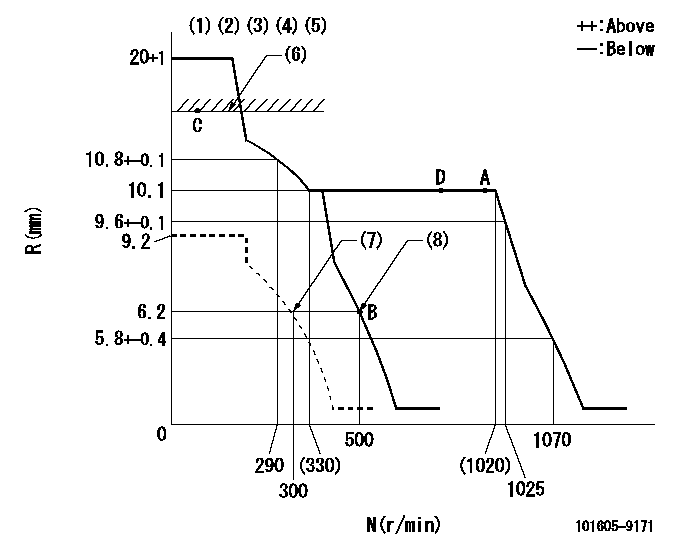
N:Pump speed
R:Rack position (mm)
(1)Target notch: K
(2)Tolerance for racks not indicated: +-0.05mm.
(3)Solenoid operation confirmation
(4)1. At idle speed (N = aa), confirm that the solenoid moves through its full stroke (stop lever angle D2).
(5)2. After confirming 1, confirm that it is pulled back to R = cc at N = bb.
(6)RACK LIMIT
(7)Set idle sub-spring
(8)Main spring setting
----------
K=11 aa=500r/min D2=(50)deg bb=100r/min cc=5mm
----------
----------
K=11 aa=500r/min D2=(50)deg bb=100r/min cc=5mm
----------
Speed control lever angle
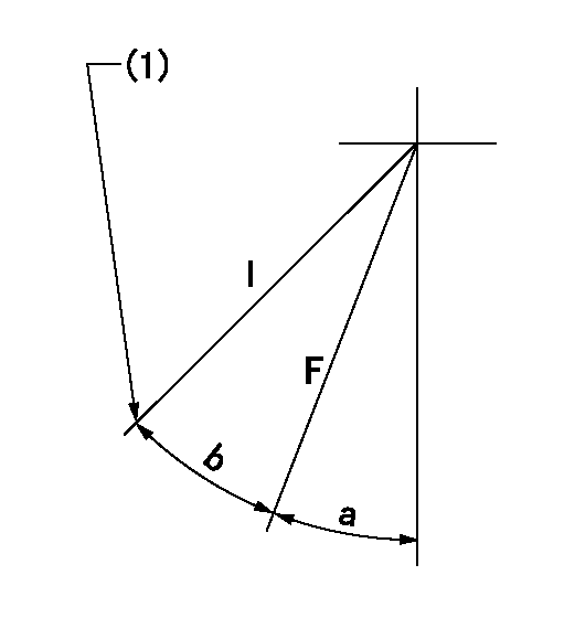
F:Full speed
I:Idle
(1)Stopper bolt setting
----------
----------
a=(13deg)+-5deg b=(25deg)+-5deg
----------
----------
a=(13deg)+-5deg b=(25deg)+-5deg
Stop lever angle

N:Pump normal
S:Stop the pump.
----------
----------
a=(26deg) b=(50deg)
----------
----------
a=(26deg) b=(50deg)
Timing setting

(1)Pump vertical direction
(2)Camshaft's key groove position at No. 6 cylinder's beginning of injection.
(3)-
(4)-
----------
----------
a=(130deg)
----------
----------
a=(130deg)
Information:
Vessels using diesel engines for main propulsion are required by the various Marine Shipping Societies to carry a supply of replacement parts on-board. Although individual requirements may differ, the following list takes into consideration the requirements of all Marine Shipping Societies and several items recommended by Caterpillar. To customize this list for your particular engine arrangement and application, contact your authorized dealer and provide the following information.1. Engine Serial Number2. Engine Arrangement Number3. Rated Horsepower4. Electrical System (12V or 24V)5. Alternator (1 or 2 belts) (from Parts Manual)6. Sea (Raw) Water Pump Part No. (from Parts Manual)7. Type of Air Filter8. Water Lines Group (from Parts Manual)9. Spin on Conditioner (Y/N)10. PCV Group No. (from Parts Manual)11. Type Water Separator12. Marine Gear ModelSuggested Replacement Parts (to be carried on board)
Category I (Intercoastal)
Parts needed for servicing minor problems at remote ports or secondary repairs offshore.* Alternator Belt* Fuel Injection Nozzles* Four Oil Filters* Four Fuel Filters* Four Zinc Rods* Four Temperature Regulators* Four Air Cleaner Elements* S O S. Bottle Group* Liquid Gasket Material* Engine Oil* Antifreeze* Coolant Corrosion Inhibitor* Coolant ConditionerCategory II (Ocean-going)
Parts needed for extended travel from a servicing port or for maintaining an extensive set of spare parts on board.Ocean-going vessels should carry all replacement parts listed in Category I as well as the items listed below. Cylinder Head Parts* One complete service head assembly.* Five cylinder head bolts and washers.* Four intake valve inserts.* Six exhaust valve inserts.* One exhaust manifold stud and nut. Valve Parts* Four intake valves.* Six exhaust valves.* Ten valve guides.* Ten rotocoil assemblies.* Ten valve springs.* Twenty-four locks. Piston Parts-Power* One piston group.* One connecting rod assembly.* One connecting rod bearing.* One piston pin.* Two piston pin retainers.* One complete set of rings for one piston.* One main bearing.* Two thrust plates.* Two main bearing cap bolts and washers.* One cylinder liner.* Three cylinder liner seals.* One cylinder liner filler band.* One oil pan gasket. Fuel System Parts* One fuel injection pump group and O-ring seal.* One set (each) of the fuel injection lines.* Four fuel nozzle assemblies, fuel bodies and nuts.* One seal and gasket for fuel nozzle adapter.* One seal, lock and adapter assembly to connect fuel lines through cylinder head.* One fuel transfer pump. Camshaft Drive Parts* One water pump idler and balance weight gear assembly.* One shaft and thrust washer for idler and balance weight gear.* One crankshaft gear.* One camshaft gear and key. Air System Parts* One complete turbocharger group.* Four turbocharger mounting studs and locknuts.* One air cleaner element.* One aftercooler core.* One each of the bypass valves for oil cooler and oil filter (valve body).* One bolt for oil pan.* One engine oil cooler core.* One marine gear oil cooler core.* One temperature regulator.* One vee belt set (if so equipped).* One jacket water pump.* One sea (raw) water pump.* One complete engine gasket kit.* One flywheel to crankshaft bolt.* One bolt for valve cover.* One repair kit for piston and rings of
Have questions with 101605-9171?
Group cross 101605-9171 ZEXEL
Daewoo
Yanmar
Dpico
Daewoo
Yanmar
101605-9171
INJECTION-PUMP ASSEMBLY