Information injection-pump assembly
BOSCH
9 400 610 692
9400610692
ZEXEL
101605-9162
1016059162
YANMAR
12760551010
12760551010

Rating:
Service parts 101605-9162 INJECTION-PUMP ASSEMBLY:
1.
_
5.
AUTOM. ADVANCE MECHANIS
6.
COUPLING PLATE
7.
COUPLING PLATE
8.
_
9.
_
10.
NOZZLE AND HOLDER ASSY
11.
Nozzle and Holder
12.
Open Pre:MPa(Kqf/cm2)
13.
NOZZLE-HOLDER
14.
NOZZLE
15.
NOZZLE SET
Cross reference number
BOSCH
9 400 610 692
9400610692
ZEXEL
101605-9162
1016059162
YANMAR
12760551010
12760551010
Zexel num
Bosch num
Firm num
Name
101605-9162
9 400 610 692
12760551010 YANMAR
INJECTION-PUMP ASSEMBLY
6CXL-DT K 14BF INJECTION PUMP ASSY PE6AD PE
6CXL-DT K 14BF INJECTION PUMP ASSY PE6AD PE
Calibration Data:
Adjustment conditions
Test oil
1404 Test oil ISO4113 or {SAEJ967d}
1404 Test oil ISO4113 or {SAEJ967d}
Test oil temperature
degC
40
40
45
Nozzle and nozzle holder
105780-8140
Bosch type code
EF8511/9A
Nozzle
105780-0000
Bosch type code
DN12SD12T
Nozzle holder
105780-2080
Bosch type code
EF8511/9
Opening pressure
MPa
17.2
Opening pressure
kgf/cm2
175
Injection pipe
Outer diameter - inner diameter - length (mm) mm 6-2-600
Outer diameter - inner diameter - length (mm) mm 6-2-600
Overflow valve
132424-0620
Overflow valve opening pressure
kPa
157
123
191
Overflow valve opening pressure
kgf/cm2
1.6
1.25
1.95
Tester oil delivery pressure
kPa
157
157
157
Tester oil delivery pressure
kgf/cm2
1.6
1.6
1.6
Direction of rotation (viewed from drive side)
Right R
Right R
Injection timing adjustment
Direction of rotation (viewed from drive side)
Right R
Right R
Injection order
6-3-5-1-
4-2
Pre-stroke
mm
3.2
3.15
3.25
Beginning of injection position
Drive side NO.1
Drive side NO.1
Difference between angles 1
Cal 6-3 deg. 60 59.5 60.5
Cal 6-3 deg. 60 59.5 60.5
Difference between angles 2
Cal 6-5 deg. 120 119.5 120.5
Cal 6-5 deg. 120 119.5 120.5
Difference between angles 3
Cal 6-1 deg. 180 179.5 180.5
Cal 6-1 deg. 180 179.5 180.5
Difference between angles 4
Cal 6-4 deg. 240 239.5 240.5
Cal 6-4 deg. 240 239.5 240.5
Difference between angles 5
Cal 6-2 deg. 300 299.5 300.5
Cal 6-2 deg. 300 299.5 300.5
Injection quantity adjustment
Adjusting point
A
Rack position
11
Pump speed
r/min
910
910
910
Each cylinder's injection qty
mm3/st.
175
171.5
178.5
Basic
*
Fixing the rack
*
Injection quantity adjustment_02
Adjusting point
C
Rack position
6.4+-0.5
Pump speed
r/min
400
400
400
Each cylinder's injection qty
mm3/st.
22.5
19.7
25.3
Fixing the rack
*
Injection quantity adjustment_03
Adjusting point
D
Rack position
-
Pump speed
r/min
100
100
100
Average injection quantity
mm3/st.
215
215
235
Fixing the lever
*
Rack limit
*
Test data Ex:
Governor adjustment
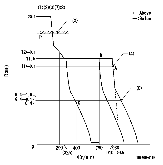
N:Pump speed
R:Rack position (mm)
(1)Notch fixed: K
(2)Tolerance for racks not indicated: +-0.05mm.
(3)RACK LIMIT
(4)Main spring setting
(5)Set idle sub-spring
(6)Solenoid operation confirmation
(7)1. At idle speed (N = aa), confirm that the solenoid moves through its full stroke (stop lever angle D2).
(8)2. After confirming 1, confirm that it is pulled back to R = cc at N = bb.
----------
K=10 aa=400r/min D2=(50)deg bb=100r/min cc=5mm
----------
----------
K=10 aa=400r/min D2=(50)deg bb=100r/min cc=5mm
----------
Speed control lever angle
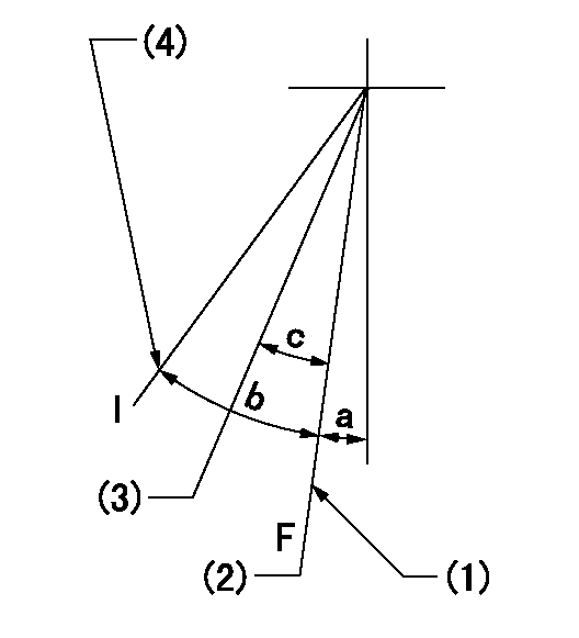
F:Full speed
I:Idle
(1)Stopper bolt setting
(2)Set the pump speed at aa
(3)When pump speed set at bb
(4)Stopper bolt setting
----------
aa=910r/min bb=750r/min
----------
a=(19deg)+-5deg b=(24deg)+-5deg c=(7deg)+-5deg
----------
aa=910r/min bb=750r/min
----------
a=(19deg)+-5deg b=(24deg)+-5deg c=(7deg)+-5deg
Stop lever angle

N:Pump normal
S:Stop the pump.
----------
----------
a=(19deg) b=(40deg)
----------
----------
a=(19deg) b=(40deg)
Timing setting

(1)Pump vertical direction
(2)Camshaft's key groove position at No. 6 cylinder's beginning of injection.
(3)-
(4)-
----------
----------
a=(130deg)
----------
----------
a=(130deg)
Information:
To Remove Injection Nozzles
Special tooling is required. See the Service Manual for this engine or your Caterpillar dealer.Turbocharger, Jacket Water Pump and Raw Water Pump
Operation of the engine until the turbocharger fails, can cause severe damage to the turbocharger's compressor wheel and/or the engine. For example, damage to the turbocharger compressor wheel could cause parts from the compressor wheel to enter the engine cylinder and cause additional damage to the piston, valve and cylinder head.A failed water pump might cause severe engine overheating problems that could result in cracks in the cylinder head, a piston seizure or other potential damage to the engine.Inspect/Rebuild or Exchange Turbocharger
Turbocharger bearing failures can cause large quantities of oil to enter the air intake and exhaust systems. Loss of engine lubricant can result in serious engine damage.Minor leakage of a turbocharger housing under extended low idle operation will not cause problems as long as no turbocharger bearing failure occurred.When a turbocharger bearing failure is accompanied by a significant engine performance loss (exhaust smoke or engine speed up at no load), DO NOT continue engine operation until the turbocharger is repaired or replaced.
1. Remove the exhaust outlet piping and inlet piping from the turbocharger. Visually check for oil leaks.2. Turn the turbine and compressor wheel by hand.3. The assembly should turn freely.4. Inspect the turbine wheel and compressor wheel for contact with the turbocharger housing.5. There should NOT be any visible signs of contact between the turbine or compressor wheel and the turbocharger housing.Check the compressor wheel for cleanliness. If only the blade side of the wheel is dirty, dirt and/or moisture is passing through the air filtering system.If oil is found only on the back side of the wheel, it indicates a turbo oil seal leak. The leak may be the result of extended engine operation at low idle or an intake air line restriction (plugged filters).Maintain the compressor wheel/turbo housing by cleaning with standard shop solvents and a soft bristle brush.6. Check the end play and bearing clearance on the turbine wheel and shaft with a dial indicator. Attach the indicator and position the pointer on the end of turbocharger shaft. Push and pull on the other end of the shaft observing the dial indicator for total reading. End play should read between 0.076 to 0.203 mm (.003 to .008 inch). If indicator reading exceeds this tolerance, the turbocharger should be rebuilt or replaced. If indicator reading is less than 0.076 mm (.003 inch), it may be an indication of carbon build-up on the turbine wheel. The turbocharger should be disassembled, cleaned and inspected.If the measurements are not within specifications, the turbocharger must be repaired or replaced.7. When installing or replacing V-band clamps, position the gap (tightening screw) down if possible so any accumulation of moisture will drain away.Turbocharger components require precision clearances and balancing due to operation at high rotational (torsional) speeds. Severe Service Applications can accelerate component wear and may suggest the need to Inspect/Repair/Replace the cartridge at reduced intervals
Have questions with 101605-9162?
Group cross 101605-9162 ZEXEL
Daewoo
Yanmar
Dpico
Daewoo
Yanmar
101605-9162
9 400 610 692
12760551010
INJECTION-PUMP ASSEMBLY
6CXL-DT
6CXL-DT