Information injection-pump assembly
BOSCH
F 019 Z10 179
f019z10179
ZEXEL
101605-9161
1016059161
Rating:
Service parts 101605-9161 INJECTION-PUMP ASSEMBLY:
1.
_
5.
AUTOM. ADVANCE MECHANIS
6.
COUPLING PLATE
7.
COUPLING PLATE
8.
_
9.
_
10.
NOZZLE AND HOLDER ASSY
11.
Nozzle and Holder
12.
Open Pre:MPa(Kqf/cm2)
13.
NOZZLE-HOLDER
14.
NOZZLE
15.
NOZZLE SET
Cross reference number
BOSCH
F 019 Z10 179
f019z10179
ZEXEL
101605-9161
1016059161
Zexel num
Bosch num
Firm num
Name
Calibration Data:
Adjustment conditions
Test oil
1404 Test oil ISO4113 or {SAEJ967d}
1404 Test oil ISO4113 or {SAEJ967d}
Test oil temperature
degC
40
40
45
Nozzle and nozzle holder
105780-8140
Bosch type code
EF8511/9A
Nozzle
105780-0000
Bosch type code
DN12SD12T
Nozzle holder
105780-2080
Bosch type code
EF8511/9
Opening pressure
MPa
17.2
Opening pressure
kgf/cm2
175
Injection pipe
Outer diameter - inner diameter - length (mm) mm 6-2-600
Outer diameter - inner diameter - length (mm) mm 6-2-600
Overflow valve
132424-0620
Overflow valve opening pressure
kPa
157
123
191
Overflow valve opening pressure
kgf/cm2
1.6
1.25
1.95
Tester oil delivery pressure
kPa
157
157
157
Tester oil delivery pressure
kgf/cm2
1.6
1.6
1.6
Direction of rotation (viewed from drive side)
Right R
Right R
Injection timing adjustment
Direction of rotation (viewed from drive side)
Right R
Right R
Injection order
6-3-5-1-
4-2
Pre-stroke
mm
3.2
3.15
3.25
Beginning of injection position
Drive side NO.1
Drive side NO.1
Difference between angles 1
Cal 6-3 deg. 60 59.5 60.5
Cal 6-3 deg. 60 59.5 60.5
Difference between angles 2
Cal 6-5 deg. 120 119.5 120.5
Cal 6-5 deg. 120 119.5 120.5
Difference between angles 3
Cal 6-1 deg. 180 179.5 180.5
Cal 6-1 deg. 180 179.5 180.5
Difference between angles 4
Cal 6-4 deg. 240 239.5 240.5
Cal 6-4 deg. 240 239.5 240.5
Difference between angles 5
Cal 6-2 deg. 300 299.5 300.5
Cal 6-2 deg. 300 299.5 300.5
Injection quantity adjustment
Adjusting point
A
Rack position
11
Pump speed
r/min
910
910
910
Each cylinder's injection qty
mm3/st.
175
171.5
178.5
Basic
*
Fixing the rack
*
Injection quantity adjustment_02
Adjusting point
C
Rack position
6.4+-0.5
Pump speed
r/min
400
400
400
Each cylinder's injection qty
mm3/st.
22.5
19.7
25.3
Fixing the rack
*
Injection quantity adjustment_03
Adjusting point
D
Rack position
-
Pump speed
r/min
100
100
100
Average injection quantity
mm3/st.
215
215
235
Fixing the lever
*
Rack limit
*
Test data Ex:
Governor adjustment
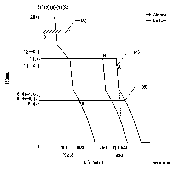
N:Pump speed
R:Rack position (mm)
(1)Notch fixed: K
(2)Tolerance for racks not indicated: +-0.05mm.
(3)RACK LIMIT
(4)Main spring setting
(5)Set idle sub-spring
(6)Solenoid operation confirmation
(7)1. At idle speed (N = aa), confirm that the solenoid moves through its full stroke (stop lever angle D2).
(8)2. After confirming 1, confirm that it is pulled back to R = cc at N = bb.
----------
K=10 aa=400r/min D2=(50)deg bb=100r/min cc=5mm
----------
----------
K=10 aa=400r/min D2=(50)deg bb=100r/min cc=5mm
----------
Speed control lever angle
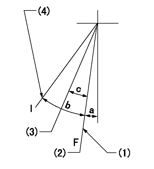
F:Full speed
I:Idle
(1)Stopper bolt setting
(2)Set the pump speed at aa
(3)When pump speed set at bb
(4)Stopper bolt setting
----------
aa=910r/min bb=750r/min
----------
a=(19deg)+-5deg b=(24deg)+-5deg c=(7deg)+-5deg
----------
aa=910r/min bb=750r/min
----------
a=(19deg)+-5deg b=(24deg)+-5deg c=(7deg)+-5deg
Stop lever angle

N:Pump normal
S:Stop the pump.
----------
----------
a=(26deg) b=(50deg)
----------
----------
a=(26deg) b=(50deg)
Timing setting

(1)Pump vertical direction
(2)Camshaft's key groove position at No. 6 cylinder's beginning of injection.
(3)-
(4)-
----------
----------
a=(130deg)
----------
----------
a=(130deg)
Information:
Flush
8. Refill the cooling system with clean water mixed with the proper concentration (six to ten percent) of Fast Acting-Type Caterpillar Cooling System Cleaner. Tighten cooling system vent cap. For proper cooling system maintenance cleaning, refer to label directions for the type of Caterpillar Cooling System Cleaner used in your cooling system.9. Start and run (operate) the engine to circulate fluid in the cooling system.10. Stop the engine and allow to cool. Loosen cooling system vent cap and drain plugs.11. Drain the cleaning solution. Flush the cooling system with clean water and a neutralizing solution until draining water is clear. Clean and install all drain plugs and/or close the drain valve. Sodium Carbonate crystals at a rate of 250 grams per 40 liters of water (1/2 pound per 10 U.S. gallon of water) may be used as a neutralizer. Repeat Steps 8 thru 11 if necessary until the draining water is clear.Install Thermostat
Caterpillar engines incorporate a shunt design cooling system and require operating the engine with a thermostat installed.If the thermostat is installed wrong, it will cause the engine to overheat.
Inspect gaskets before assembly and replace if worn or damaged.12. Install a new seal in the thermostat housing and install a new thermostat.13. Install a new gasket and the thermostat housing on the engine cylinder head.14. Install the cooling system connections and tighten the hose or piping clamps.Fill
All water is corrosive at engine operating temperature. The cooling system should be protected with cooling system conditioner at all times. Use Caterpillar liquid cooling system conditioner to treat the coolant mixture.
Refer to the Cooling System Specifications section of this publication for all information regarding about the appropriate maintenance of the cooling system or contact your Caterpillar dealer for assistance. See Refill Capacities chart in this publication for the capacity of your engine's system.15. Be certain all drain plugs are clean and installed. Mix a solution of acceptable water and Caterpillar Antifreeze (which contains supplemental coolant additive).16. Start and run the engine with the cooling system vent cap loosened. Operate the engine and allow the coolant to warm, the thermostats to open and the coolant level to stabilize. Inspect for leaks and proper operating temperature.
To prevent engine damage, never add coolant to an overheated engine. Allow the engine to cool first.
17. Add coolant mixture if necessary to bring the coolant to within 13 mm (1/2 inch) below the bottom of the fill tube or the correct level on the sight glass, if equipped. Upon initial fill the sight gauge can indicate an incorrect coolant level. Be sure the coolant is to the bottom of the fill tube. Recheck the coolant level and fill the cooling system to the bottom of the fill tube if the system was low.
In cold weather, frequently check the specific gravity of the coolant solution to ensure adequate protection.If the engine is to be stored in, or shipped to an area with freezing temperatures, the cooling system must be either protected to the lowest expected outside temperature