Information injection-pump assembly
ZEXEL
101605-9160
1016059160
Rating:
Service parts 101605-9160 INJECTION-PUMP ASSEMBLY:
1.
_
5.
AUTOM. ADVANCE MECHANIS
6.
COUPLING PLATE
7.
COUPLING PLATE
8.
_
9.
_
10.
NOZZLE AND HOLDER ASSY
11.
Nozzle and Holder
12.
Open Pre:MPa(Kqf/cm2)
13.
NOZZLE-HOLDER
14.
NOZZLE
15.
NOZZLE SET
Cross reference number
ZEXEL
101605-9160
1016059160
Zexel num
Bosch num
Firm num
Name
101605-9160
INJECTION-PUMP ASSEMBLY
14BF PE6AD PE
14BF PE6AD PE
Calibration Data:
Adjustment conditions
Test oil
1404 Test oil ISO4113 or {SAEJ967d}
1404 Test oil ISO4113 or {SAEJ967d}
Test oil temperature
degC
40
40
45
Nozzle and nozzle holder
105780-8140
Bosch type code
EF8511/9A
Nozzle
105780-0000
Bosch type code
DN12SD12T
Nozzle holder
105780-2080
Bosch type code
EF8511/9
Opening pressure
MPa
17.2
Opening pressure
kgf/cm2
175
Injection pipe
Outer diameter - inner diameter - length (mm) mm 6-2-600
Outer diameter - inner diameter - length (mm) mm 6-2-600
Overflow valve
132424-0620
Overflow valve opening pressure
kPa
157
123
191
Overflow valve opening pressure
kgf/cm2
1.6
1.25
1.95
Tester oil delivery pressure
kPa
157
157
157
Tester oil delivery pressure
kgf/cm2
1.6
1.6
1.6
Direction of rotation (viewed from drive side)
Right R
Right R
Injection timing adjustment
Direction of rotation (viewed from drive side)
Right R
Right R
Injection order
6-3-5-1-
4-2
Pre-stroke
mm
3.2
3.15
3.25
Beginning of injection position
Drive side NO.1
Drive side NO.1
Difference between angles 1
Cal 6-3 deg. 60 59.5 60.5
Cal 6-3 deg. 60 59.5 60.5
Difference between angles 2
Cal 6-5 deg. 120 119.5 120.5
Cal 6-5 deg. 120 119.5 120.5
Difference between angles 3
Cal 6-1 deg. 180 179.5 180.5
Cal 6-1 deg. 180 179.5 180.5
Difference between angles 4
Cal 6-4 deg. 240 239.5 240.5
Cal 6-4 deg. 240 239.5 240.5
Difference between angles 5
Cal 6-2 deg. 300 299.5 300.5
Cal 6-2 deg. 300 299.5 300.5
Injection quantity adjustment
Adjusting point
A
Rack position
11
Pump speed
r/min
910
910
910
Each cylinder's injection qty
mm3/st.
175
171.5
178.5
Basic
*
Fixing the rack
*
Injection quantity adjustment_02
Adjusting point
C
Rack position
6.4+-0.5
Pump speed
r/min
400
400
400
Each cylinder's injection qty
mm3/st.
22.5
19.7
25.3
Fixing the rack
*
Injection quantity adjustment_03
Adjusting point
D
Rack position
-
Pump speed
r/min
100
100
100
Average injection quantity
mm3/st.
215
215
235
Fixing the lever
*
Rack limit
*
Test data Ex:
Governor adjustment
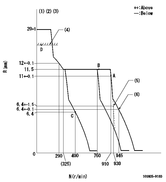
N:Pump speed
R:Rack position (mm)
(1)Notch fixed: K
(2)Tolerance for racks not indicated: +-0.05mm.
(3)Confirm that the rack is pulled back to R = R1 or less at solenoid operation (N = 0).
(4)RACK LIMIT
(5)Main spring setting
(6)Set idle sub-spring
----------
K=10 R1=5.9mm
----------
----------
K=10 R1=5.9mm
----------
Speed control lever angle
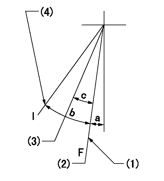
F:Full speed
I:Idle
(1)Stopper bolt setting
(2)Set the pump speed at aa
(3)When pump speed set at bb
(4)Stopper bolt setting
----------
aa=900r/min bb=750r/min
----------
a=(19deg)+-5deg b=(24deg)+-5deg c=(7deg)+-5deg
----------
aa=900r/min bb=750r/min
----------
a=(19deg)+-5deg b=(24deg)+-5deg c=(7deg)+-5deg
Stop lever angle

N:Pump normal
S:Stop the pump.
----------
----------
a=(26deg) b=(50deg)
----------
----------
a=(26deg) b=(50deg)
Timing setting

(1)Pump vertical direction
(2)Camshaft's key groove position at No. 6 cylinder's beginning of injection.
(3)-
(4)-
----------
----------
a=(130deg)
----------
----------
a=(130deg)
Information:
You must read and understand the warnings and instructions contained in the Safety section of this manual before performing any operation or maintenance procedures.Before proceeding with this maintenance interval, perform previous maintenance intervals and Daily maintenance requirements. Perform the maintenance at the interval listed in the Maintenance Schedule for your engine.
For maintenance of the following components in this interval, refer to the OEM manual for maintenance instructions. The following are basic suggestions and instructions.
Marine Gear
Drain Oil
With the oil warm and the engine stopped, drain the transmission.1. Remove the transmission drain plug and allow the oil to drain. Obtain an oil sample for analysis.2. Clean and install the drain plug.If a Sump Pump is Used to Drain Oil
a. Connect a drain line and container to top outlet (A) of pump.b. Be sure valve (B) on the engine oil pan line is closed. Marks on the valve must be turned at right angles to the direction of the engine oil line. c. Open valve (C) on the transmission oil line. The marks on this valve must be turned so that one mark points to the pump and the second mark points to the transmission.d. Operate the sump pump (D) handle until the transmission is empty.e. Close the sump pump valve on the oil line to the transmission.Change Filters
1. Remove transmission oil filter housing drain plug (if equipped). Allow the oil to drain into the marine gear transmission sump.2. Remove filter assembly. Disassemble and discard the element.3. Clean the filter housing and assembly parts with clean, nonflammable solvent. Clean and install the filter housing drain plug.4. Inspect any retainer plates and/or seals. Install new seals if necessary.5. Assemble and install a new filter element assembly. Tighten all bolts.6. Operate the sump pump handle until the transmission is empty. Close the sump pump valve on the oil line to the transmission.Clean the Oil Strainer
1. Remove the strainer cover and plug. Remove the spring washer, strainer screen and magnetic screen tube (if equipped).2. Wash the strainer and magnetic screen tube with clean, nonflammable solvent. If a magnet is broken, install the new magnet properly. The North (N) poles and South (S) poles of the magnets are adjacent to each other so that they repel instead of attract: S-N, N-S, S-N.3. Inspect the strainer, plug and the cover seal for damage. Use new parts if used ones are damaged.4. Install the magnetic screen tube, strainer, spring washer, seal, cover and plug.Clean the Breather (All Marine Transmissions)
1. Remove the breather.2. Clean the breather with clean, nonflammable solvent.3. Install the breather.Fill the Transmission
Be sure both sump pump valves (one to the transmission and one to the engine oil pan) are closed. Otherwise a transfer of oil may occur during sump pump operation and damage could result.
1. Be sure the marine gear drain plug has been installed, or the sump pump valve (C) on the oil line to the marine gear drain line has been closed.2. Fill the marine gear to the FULL mark on the
Have questions with 101605-9160?
Group cross 101605-9160 ZEXEL
Daewoo
Yanmar
Dpico
Daewoo
101605-9160
INJECTION-PUMP ASSEMBLY