Information injection-pump assembly
BOSCH
9 400 615 371
9400615371
ZEXEL
101605-9152
1016059152

Rating:
Include in #1:
101402-4350
as _
Cross reference number
BOSCH
9 400 615 371
9400615371
ZEXEL
101605-9152
1016059152
Zexel num
Bosch num
Firm num
Name
101605-9152
9 400 615 371
DAEWOO
INJECTION-PUMP ASSEMBLY
D1146 K
D1146 K
Calibration Data:
Adjustment conditions
Test oil
1404 Test oil ISO4113 or {SAEJ967d}
1404 Test oil ISO4113 or {SAEJ967d}
Test oil temperature
degC
40
40
45
Nozzle and nozzle holder
105780-8140
Bosch type code
EF8511/9A
Nozzle
105780-0000
Bosch type code
DN12SD12T
Nozzle holder
105780-2080
Bosch type code
EF8511/9
Opening pressure
MPa
17.2
Opening pressure
kgf/cm2
175
Injection pipe
Outer diameter - inner diameter - length (mm) mm 6-2-600
Outer diameter - inner diameter - length (mm) mm 6-2-600
Overflow valve
131424-1520
Overflow valve opening pressure
kPa
157
123
191
Overflow valve opening pressure
kgf/cm2
1.6
1.25
1.95
Tester oil delivery pressure
kPa
157
157
157
Tester oil delivery pressure
kgf/cm2
1.6
1.6
1.6
Direction of rotation (viewed from drive side)
Right R
Right R
Injection timing adjustment
Direction of rotation (viewed from drive side)
Right R
Right R
Injection order
6-2-4-1-
5-3
Pre-stroke
mm
4.6
4.55
4.65
Beginning of injection position
Drive side NO.1
Drive side NO.1
Difference between angles 1
Cal 6-2 deg. 60 59.5 60.5
Cal 6-2 deg. 60 59.5 60.5
Difference between angles 2
Cal 6-4 deg. 120 119.5 120.5
Cal 6-4 deg. 120 119.5 120.5
Difference between angles 3
Cal 6-1 deg. 180 179.5 180.5
Cal 6-1 deg. 180 179.5 180.5
Difference between angles 4
Cal 6-5 deg. 240 239.5 240.5
Cal 6-5 deg. 240 239.5 240.5
Difference between angles 5
Cal 6-3 deg. 300 299.5 300.5
Cal 6-3 deg. 300 299.5 300.5
Injection quantity adjustment
Adjusting point
A
Rack position
10.5
Pump speed
r/min
1100
1100
1100
Average injection quantity
mm3/st.
91.2
89.2
93.2
Max. variation between cylinders
%
0
-2
2
Basic
*
Fixing the lever
*
Injection quantity adjustment_02
Adjusting point
B
Rack position
7.7+-0.5
Pump speed
r/min
370
370
370
Average injection quantity
mm3/st.
11.5
10
13
Max. variation between cylinders
%
0
-15
15
Fixing the rack
*
Test data Ex:
Governor adjustment
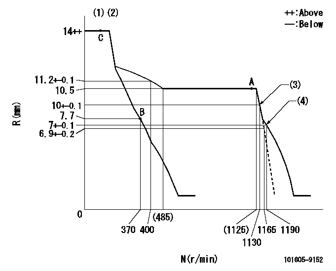
N:Pump speed
R:Rack position (mm)
(1)Target notch: K
(2)Tolerance for racks not indicated: +-0.05mm.
(3)Main spring setting
(4)Set idle sub-spring
----------
K=7
----------
----------
K=7
----------
Speed control lever angle
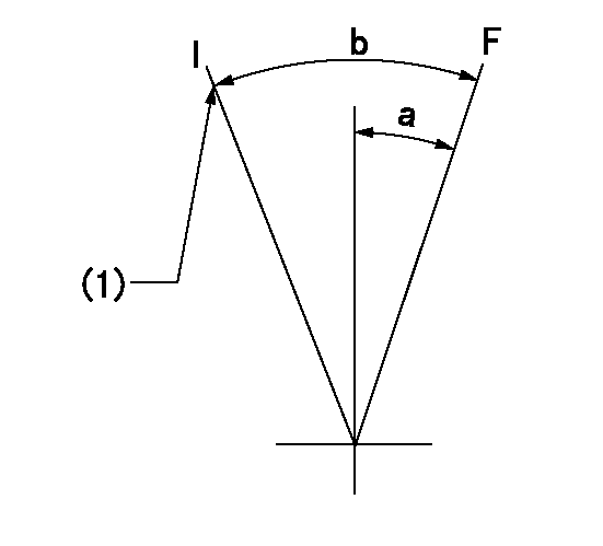
F:Full speed
I:Idle
(1)Stopper bolt setting
----------
----------
a=1deg+-5deg b=24deg+-5deg
----------
----------
a=1deg+-5deg b=24deg+-5deg
Stop lever angle

N:Pump normal
S:Stop the pump.
----------
----------
a=19deg+-5deg b=53deg+-5deg
----------
----------
a=19deg+-5deg b=53deg+-5deg
Timing setting
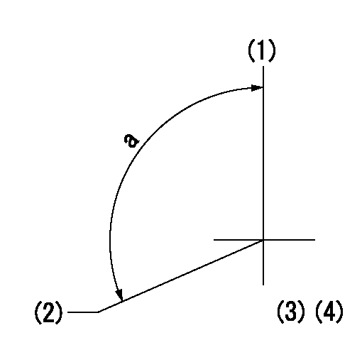
(1)Pump vertical direction
(2)Camshaft's key groove position at No. 6 cylinder's beginning of injection.
(3)-
(4)-
----------
----------
a=(120deg)
----------
----------
a=(120deg)
Information:
Belts, Hoses and Clamps
Inspect/Replace Accessory Drive Belts
Inspect the condition and adjustment of alternator drive belts. Examine belts for wear and replace if any signs of wear are present. Loose or worn pulley grooves cause belt slippage and low accessory drive speed.If belts are too loose, they vibrate enough to cause unnecessary wear on the belts and pulleys and possibly slip enough to cause overheating. If belts are too tight, unnecessary stresses are placed upon the pulley bearings and belts which can shorten the life of both.If one belt in a set requires replacement, always install a new matched set of belts. Never replace just the worn belt. If only the worn belt is replaced, the new belt will carry all the load, as it will not be stretched as much as the older belts. All the belts will fail in rapid succession.Adjust
1. Remove belt guard. Inspect the condition and adjustment of alternator belts and accessory drive belts, if equipped.2. To check the belt tension, apply 110 Newton (25 lb) force, perpendicular to the belt, midway between the driving and driven pulley. Measure the belt deflection. Correctly adjusted belts will deflect 13 to 20 mm (1/2 to 7/8 inch). Adjust the belt tension as required.If belt does not require replacement or adjustment, install the belt guard. If belt requires adjustment or replacement, do not install the belt guard.3. Loosen the mounting pivot bolt (1). Loosen the adjustment nut(s) (2).4. Adjust the alternator in or out by either tightening or loosening adjustment nut(s) as required to obtain the correct adjustment.5. Tighten bolts (1) and (2). Check the belt tension. Install the belt guard.If new belts are installed, check belt adjustment again after 30 minutes of engine operation. Repeat belt tightening if required.Adjust Accessory Drive Belts
If engine is equipped with any other belt driven equipment, check and adjust them as required.Inspect/Replace Hoses and Clamps
Hose replacement prior to failure is a good preventive maintenance practice. Replacing a hose before it fails reduces the chances for unscheduled downtime. By replacing a hose that is cracked, soft or leaking, major repairs will be avoided that could result in a severe engine overheating problem.* Inspect all hoses for leaks due to cracking, softness and loose clamps.* Replace hoses that are cracked or soft and tighten loose clamps. See the Torque for Standard Hose Clamps chart in the Torque Specifications section of this publication for the appropriate torque. For constant torque hose clamps, see the Torque Specifications section in this publication.Engine Valve Lash
Check/Adjust
To prevent possible injury, do not use the starting motor to turn the flywheel. Be sure the starting motors are disabled and engine cannot be started while this maintenance is being performed.Hot engine components can cause burns. Allow additional time for the engine to cool before measuring valve lash.
Measure the valve lash with the engine stopped. To obtain an accurate measurement, allow at least 20 minutes for the valves to cool to engine cylinder head and block temperature.
Initial valve lash adjustment (At First Oil
Have questions with 101605-9152?
Group cross 101605-9152 ZEXEL
Daewoo
Yanmar
Dpico
Daewoo
101605-9152
9 400 615 371
INJECTION-PUMP ASSEMBLY
D1146
D1146