Information injection-pump assembly
ZEXEL
101605-9150
1016059150
Rating:
Service parts 101605-9150 INJECTION-PUMP ASSEMBLY:
1.
_
5.
AUTOM. ADVANCE MECHANIS
6.
COUPLING PLATE
7.
COUPLING PLATE
8.
_
9.
_
10.
NOZZLE AND HOLDER ASSY
11.
Nozzle and Holder
12.
Open Pre:MPa(Kqf/cm2)
13.
NOZZLE-HOLDER
14.
NOZZLE
15.
NOZZLE SET
Cross reference number
ZEXEL
101605-9150
1016059150
Zexel num
Bosch num
Firm num
Name
Calibration Data:
Adjustment conditions
Test oil
1404 Test oil ISO4113 or {SAEJ967d}
1404 Test oil ISO4113 or {SAEJ967d}
Test oil temperature
degC
40
40
45
Nozzle and nozzle holder
105780-8140
Bosch type code
EF8511/9A
Nozzle
105780-0000
Bosch type code
DN12SD12T
Nozzle holder
105780-2080
Bosch type code
EF8511/9
Opening pressure
MPa
17.2
Opening pressure
kgf/cm2
175
Injection pipe
Outer diameter - inner diameter - length (mm) mm 6-2-600
Outer diameter - inner diameter - length (mm) mm 6-2-600
Overflow valve
131424-1520
Overflow valve opening pressure
kPa
157
123
191
Overflow valve opening pressure
kgf/cm2
1.6
1.25
1.95
Tester oil delivery pressure
kPa
157
157
157
Tester oil delivery pressure
kgf/cm2
1.6
1.6
1.6
Direction of rotation (viewed from drive side)
Right R
Right R
Injection timing adjustment
Direction of rotation (viewed from drive side)
Right R
Right R
Injection order
6-2-4-1-
5-3
Pre-stroke
mm
4.6
4.55
4.65
Beginning of injection position
Drive side NO.1
Drive side NO.1
Difference between angles 1
Cal 6-2 deg. 60 59.5 60.5
Cal 6-2 deg. 60 59.5 60.5
Difference between angles 2
Cal 6-4 deg. 120 119.5 120.5
Cal 6-4 deg. 120 119.5 120.5
Difference between angles 3
Cal 6-1 deg. 180 179.5 180.5
Cal 6-1 deg. 180 179.5 180.5
Difference between angles 4
Cal 6-5 deg. 240 239.5 240.5
Cal 6-5 deg. 240 239.5 240.5
Difference between angles 5
Cal 6-3 deg. 300 299.5 300.5
Cal 6-3 deg. 300 299.5 300.5
Injection quantity adjustment
Adjusting point
A
Rack position
10.5
Pump speed
r/min
1100
1100
1100
Average injection quantity
mm3/st.
91.2
89.2
93.2
Max. variation between cylinders
%
0
-2
2
Basic
*
Fixing the lever
*
Injection quantity adjustment_02
Adjusting point
B
Rack position
7.7+-0.5
Pump speed
r/min
370
370
370
Average injection quantity
mm3/st.
11.5
10.2
12.8
Max. variation between cylinders
%
0
-15
15
Fixing the rack
*
Test data Ex:
Governor adjustment
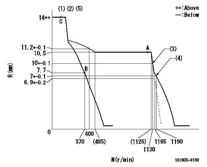
N:Pump speed
R:Rack position (mm)
(1)Target notch: K
(2)Tolerance for racks not indicated: +-0.05mm.
(3)Main spring setting
(4)Set idle sub-spring
(5)Microswitch adjustment unnecessary.
----------
K=7
----------
----------
K=7
----------
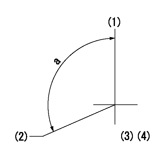
Speed control lever angle

F:Full speed
I:Idle
(1)Stopper bolt setting
----------
----------
a=24deg+-5deg b=1deg+-5deg
----------
----------
a=24deg+-5deg b=1deg+-5deg
Stop lever angle

N:Pump normal
S:Stop the pump.
----------
----------
a=19deg+-5deg b=53deg+-5deg
----------
----------
a=19deg+-5deg b=53deg+-5deg
Timing setting
(1)Pump vertical direction
(2)Camshaft's key groove position at No. 6 cylinder's beginning of injection.
(3)-
(4)-
----------
----------
a=(120deg)
----------
----------
a=(120deg)
Information:
You must read and understand the warnings and instructions contained in the Safety section of this manual before performing any operation or maintenance procedures.This maintenance is to be performed at the interval specified in the Maintenance Schedule for the engine being maintained.Before proceeding with this maintenance, first perform Daily maintenance requirements.Zinc Rods
Zinc rods are inserted in the engine's raw water cooling system to help prevent the corrosive action of salt (sea) water. The reaction of the zinc to the sea (raw) water causes the rods to deteriorate, instead of more critical engine cooling system parts.Therefore, the zinc rods must be inspected every 50 service hours, and replaced when they have deteriorated.Depending on the engine and attachments, their location may be in the oil cooler heat exchanger bonnet, raw water heat exchanger bonnet, aftercooler lines, raw water pump and/or in the raw water lines.Inspect
Removing Old Zinc Rods
1. Remove and observe condition of all zinc rods. They are painted red for easy identification. 2. Tap the zinc rods lightly with a hammer. If a rod has deteriorated, or flakes apart when tapped, install a new zinc rod.Installing New Zinc Rods
1. Unscrew or drill the existing rod from the plug base.2. Apply 9S3263 Thread Lock to the internal threads of the plug(s) holding the zinc rod(s). Install new rod(s) in the plug base(s).3. Coat the external pipe threads with 5P3413 Pipe Sealant and install the plug(s) into their proper locations in the raw water system.Marine Gear
Drain Oil and Replace Filter
With the oil warm and the engine stopped, drain the oil and replace oil filter element on a new or rebuilt marine gear at the first 50 Hour interval to ensure draining of possible large debris and particles from the oil and gear housing.Drain and change filter element with the oil warm and the engine stopped to allow for the draining of waste particles that are suspended in the oil. Suspended waste particles will settle on the bottom and will not be removed with the draining oil if the oil is cold.Failure to follow this recommended procedure would result in these waste particles being recirculated through your marine gear system with the new oil. Refer to the topic in the Every 1000 Hour maintenance interval in this manual for instructions and procedure.For lubrication and maintenance requirements for your marine gear model, refer to the OEM and/or vessel manufacturer's recommendations.Marine Gear Operation, Maintenance, Warranty & Parts Support
Caterpillar encourages customers to refer to their Caterpillar dealer and/or marine gear OEM dealer for information regarding operation and maintenance for the transmission.All warranty and parts support for the marine gear (including installation and service problem resolution) will be the responsibility of the selling dealer and the marine gear OEM.Air Tank
Drain Water and Sediment
When required, or at least on a weekly basis, open the drain valve on the air tank and drain the water and sediment. Close the valve.