Information injection-pump assembly
ZEXEL
101605-9120
1016059120

Rating:
Cross reference number
ZEXEL
101605-9120
1016059120
Zexel num
Bosch num
Firm num
Name
Calibration Data:
Adjustment conditions
Test oil
1404 Test oil ISO4113 or {SAEJ967d}
1404 Test oil ISO4113 or {SAEJ967d}
Test oil temperature
degC
40
40
45
Nozzle and nozzle holder
105780-8140
Bosch type code
EF8511/9A
Nozzle
105780-0000
Bosch type code
DN12SD12T
Nozzle holder
105780-2080
Bosch type code
EF8511/9
Opening pressure
MPa
17.2
Opening pressure
kgf/cm2
175
Injection pipe
Outer diameter - inner diameter - length (mm) mm 6-2-600
Outer diameter - inner diameter - length (mm) mm 6-2-600
Overflow valve
131424-1520
Overflow valve opening pressure
kPa
157
123
191
Overflow valve opening pressure
kgf/cm2
1.6
1.25
1.95
Tester oil delivery pressure
kPa
157
157
157
Tester oil delivery pressure
kgf/cm2
1.6
1.6
1.6
Direction of rotation (viewed from drive side)
Right R
Right R
Injection timing adjustment
Direction of rotation (viewed from drive side)
Right R
Right R
Injection order
1-5-3-6-
2-4
Pre-stroke
mm
3.4
3.35
3.45
Beginning of injection position
Drive side NO.1
Drive side NO.1
Difference between angles 1
Cal 1-5 deg. 60 59.5 60.5
Cal 1-5 deg. 60 59.5 60.5
Difference between angles 2
Cal 1-3 deg. 120 119.5 120.5
Cal 1-3 deg. 120 119.5 120.5
Difference between angles 3
Cal 1-6 deg. 180 179.5 180.5
Cal 1-6 deg. 180 179.5 180.5
Difference between angles 4
Cyl.1-2 deg. 240 239.5 240.5
Cyl.1-2 deg. 240 239.5 240.5
Difference between angles 5
Cal 1-4 deg. 300 299.5 300.5
Cal 1-4 deg. 300 299.5 300.5
Injection quantity adjustment
Adjusting point
A
Rack position
9.4
Pump speed
r/min
1100
1100
1100
Average injection quantity
mm3/st.
77
75.5
78.5
Max. variation between cylinders
%
0
-2.5
2.5
Basic
*
Fixing the lever
*
Boost pressure
kPa
38.7
38.7
Boost pressure
mmHg
290
290
Injection quantity adjustment_02
Adjusting point
-
Rack position
6.6+-0.5
Pump speed
r/min
400
400
400
Average injection quantity
mm3/st.
9.4
8.1
10.7
Max. variation between cylinders
%
0
-14
14
Fixing the rack
*
Boost pressure
kPa
0
0
0
Boost pressure
mmHg
0
0
0
Remarks
Adjust only variation between cylinders; adjust governor according to governor specifications.
Adjust only variation between cylinders; adjust governor according to governor specifications.
Injection quantity adjustment_03
Adjusting point
E
Rack position
-
Pump speed
r/min
100
100
100
Average injection quantity
mm3/st.
90
90
110
Fixing the lever
*
Boost pressure
kPa
0
0
0
Boost pressure
mmHg
0
0
0
Rack limit
*
Boost compensator adjustment
Pump speed
r/min
500
500
500
Rack position
8.9
Boost pressure
kPa
12
9.3
14.7
Boost pressure
mmHg
90
70
110
Boost compensator adjustment_02
Pump speed
r/min
500
500
500
Rack position
(9.4)
Boost pressure
kPa
25.3
18.6
32
Boost pressure
mmHg
190
140
240
Test data Ex:
Governor adjustment
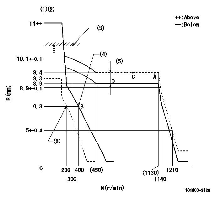
N:Pump speed
R:Rack position (mm)
(1)Target notch: K
(2)Tolerance for racks not indicated: +-0.05mm.
(3)RACK LIMIT
(4)Main spring setting
(5)Boost compensator stroke: BCL
(6)Set idle sub-spring
----------
K=5 BCL=(0.5)+-0.1mm
----------
----------
K=5 BCL=(0.5)+-0.1mm
----------
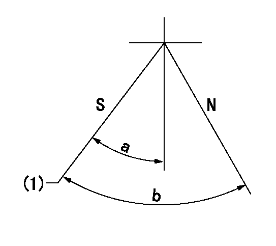
Speed control lever angle

F:Full speed
I:Idle
(1)Stopper bolt setting
----------
----------
a=(1deg)+-5deg b=(19deg)+-5deg
----------
----------
a=(1deg)+-5deg b=(19deg)+-5deg
Stop lever angle
N:Pump normal
S:Stop the pump.
(1)Pump speed aa and rack position bb (to be sealed at delivery)
----------
aa=0r/min bb=1-0.2mm
----------
a=21deg+-5deg b=(55deg)
----------
aa=0r/min bb=1-0.2mm
----------
a=21deg+-5deg b=(55deg)
Timing setting

(1)Pump vertical direction
(2)Position of gear mark 'CC' at No 1 cylinder's beginning of injection
(3)B.T.D.C.: aa
(4)-
----------
aa=18deg
----------
a=(90deg)
----------
aa=18deg
----------
a=(90deg)
Information:
Operate the controls ONLY with the engine running. Report any needed repairs noted during operation.
Engine and Marine Transmission Operation
Operate a cool engine at low load. After normal oil pressure is reached and the temperature gauges begin to move, the engine may be operated at full load.Transmission Selector Lever
Typical ExampleFull power is transferred from the engine through the marine transmission, in either forward (1) or reverse (3) rotation, to the propeller shaft. The engine transmissions can be operated by mechanical, hydraulic, pneumatic or electrically actuated controls for the forward and reverse drives.A control valve directs the flow of oil to either the forward or reverse clutch (for forward or reverse operation). The valve is operated by a selector lever, which can be remotely operated (from the pilot station) or operated manually from the transmission (in the engine room).Moving and Getting Underway
The marine transmission selector valve is usually operated from the pilot house. It can also be operated at the marine transmission. Pilot house controls must be adjusted so as to permit full travel of the selector lever on the marine transmission, and full engagement of the clutch plates.To get underway after the engine has started and is warm:1. Fully engage the marine transmission control lever in the desired direction of travel. Allow one second before increasing engine speed.2. Wait a sufficient amount of time to allow complete engagement of the clutch.3. Gradually increase engine speed as required.Docking or Traveling (Direction Change)
The engine torque must be able to overcome the propeller and drive line inertia, the marine transmission inertia and the propeller slip stream torque. 1. Reduce engine speed to LOW IDLE.
Do not shift across NEUTRAL position without a few seconds delay. When reversing direction of travel (propeller rotation), stop at least two seconds in the position to allow the clutch plates to completely disengage, and the propeller to stop turning. A direct through-shift will cause severe shock loads to the engine, marine gear and hull. Also, it can cause the engine to reverse its rotation. If the engine reverses rotation, the engine and marine transmission oil pumps will be running opposite normal rotation. Oil will be pulled from the bearings and cause severe damage.
2. Move the marine transmission control lever to the NEUTRAL position.3. Move the marine transmission control lever to the engaged position. Wait a sufficient amount of time to allow complete engagement of the clutch before gradually increasing engine speed. The marine gear rotation should not be changed at full engine speed. To prevent the propeller from stalling or reversing the engine's rotation gradually increase engine speed as the clutch is engaged. A sequenced engine control system may be required. This equipment consists of a throttle boost with an optional shaft brake. The throttle boost system momentarily increases engine speed as the marine transmission selector lever is moved from NEUTRAL to the engaged position. The throttle boost is released upon completion of clutch engagement. The governor setting then regulates the engine speed.With the selector lever in the