Information injection-pump assembly
ZEXEL
101605-9060
1016059060
NISSAN-DIESEL
1679095018
1679095018

Rating:
Service parts 101605-9060 INJECTION-PUMP ASSEMBLY:
1.
_
5.
AUTOM. ADVANCE MECHANIS
7.
COUPLING PLATE
8.
_
9.
_
11.
Nozzle and Holder
16600-95011
12.
Open Pre:MPa(Kqf/cm2)
19.6{200}
15.
NOZZLE SET
Cross reference number
ZEXEL
101605-9060
1016059060
NISSAN-DIESEL
1679095018
1679095018
Zexel num
Bosch num
Firm num
Name
Calibration Data:
Adjustment conditions
Test oil
1404 Test oil ISO4113 or {SAEJ967d}
1404 Test oil ISO4113 or {SAEJ967d}
Test oil temperature
degC
40
40
45
Nozzle and nozzle holder
105780-8140
Bosch type code
EF8511/9A
Nozzle
105780-0000
Bosch type code
DN12SD12T
Nozzle holder
105780-2080
Bosch type code
EF8511/9
Opening pressure
MPa
17.2
Opening pressure
kgf/cm2
175
Injection pipe
Outer diameter - inner diameter - length (mm) mm 6-2-600
Outer diameter - inner diameter - length (mm) mm 6-2-600
Overflow valve
131424-1520
Overflow valve opening pressure
kPa
157
123
191
Overflow valve opening pressure
kgf/cm2
1.6
1.25
1.95
Tester oil delivery pressure
kPa
157
157
157
Tester oil delivery pressure
kgf/cm2
1.6
1.6
1.6
Direction of rotation (viewed from drive side)
Right R
Right R
Injection timing adjustment
Direction of rotation (viewed from drive side)
Right R
Right R
Injection order
1-4-2-6-
3-5
Pre-stroke
mm
2.75
2.7
2.8
Beginning of injection position
Drive side NO.1
Drive side NO.1
Difference between angles 1
Cal 1-4 deg. 60 59.5 60.5
Cal 1-4 deg. 60 59.5 60.5
Difference between angles 2
Cyl.1-2 deg. 120 119.5 120.5
Cyl.1-2 deg. 120 119.5 120.5
Difference between angles 3
Cal 1-6 deg. 180 179.5 180.5
Cal 1-6 deg. 180 179.5 180.5
Difference between angles 4
Cal 1-3 deg. 240 239.5 240.5
Cal 1-3 deg. 240 239.5 240.5
Difference between angles 5
Cal 1-5 deg. 300 299.5 300.5
Cal 1-5 deg. 300 299.5 300.5
Injection quantity adjustment
Adjusting point
A
Rack position
10.9
Pump speed
r/min
750
750
750
Average injection quantity
mm3/st.
107
105.5
108.5
Max. variation between cylinders
%
0
-2
2
Basic
*
Fixing the lever
*
Boost pressure
kPa
76
76
Boost pressure
mmHg
570
570
Injection quantity adjustment_02
Adjusting point
B
Rack position
10.1
Pump speed
r/min
1115
1115
1115
Average injection quantity
mm3/st.
95.4
92.4
98.4
Fixing the rack
*
Boost pressure
kPa
76
76
Boost pressure
mmHg
570
570
Injection quantity adjustment_03
Adjusting point
C
Rack position
R1(9.7)
Pump speed
r/min
600
600
600
Average injection quantity
mm3/st.
79
77
81
Fixing the lever
*
Boost pressure
kPa
0
0
0
Boost pressure
mmHg
0
0
0
Injection quantity adjustment_04
Adjusting point
D
Rack position
6.4+-0.5
Pump speed
r/min
400
400
400
Average injection quantity
mm3/st.
10.5
9
12
Max. variation between cylinders
%
0
-10
10
Fixing the rack
*
Boost pressure
kPa
0
0
0
Boost pressure
mmHg
0
0
0
Boost compensator adjustment
Pump speed
r/min
600
600
600
Rack position
R1(9.7)
Boost pressure
kPa
20
17.3
22.7
Boost pressure
mmHg
150
130
170
Boost compensator adjustment_02
Pump speed
r/min
600
600
600
Rack position
10.9
Boost pressure
kPa
62.7
62.7
62.7
Boost pressure
mmHg
470
470
470
Test data Ex:
Governor adjustment

N:Pump speed
R:Rack position (mm)
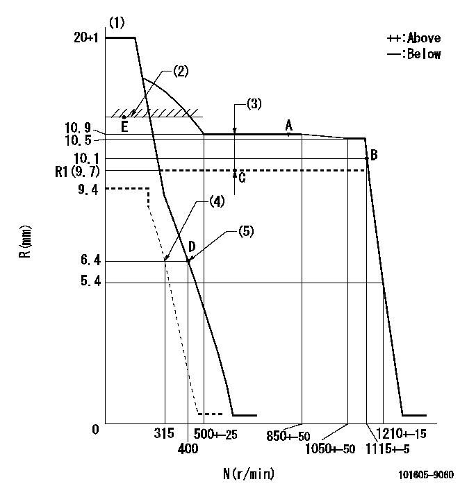
(1)Target notch: K
(2)Boost compensator excessive fuel lever at operation (at 0 boost pressure): L1
(3)Boost compensator stroke: BCL
(4)Set idle sub-spring
(5)Main spring setting
----------
K=11 L1=11.5+-0.2mm BCL=(1.2)mm
----------
----------
K=11 L1=11.5+-0.2mm BCL=(1.2)mm
----------
Speed control lever angle

F:Full speed
I:Idle
(1)Stopper bolt setting
----------
----------
a=7deg+-5deg b=17deg+-5deg
----------
----------
a=7deg+-5deg b=17deg+-5deg
Stop lever angle

N:Pump normal
S:Stop the pump.
----------
----------
a=26.5deg+-5deg b=53deg+-5deg
----------
----------
a=26.5deg+-5deg b=53deg+-5deg
0000001101

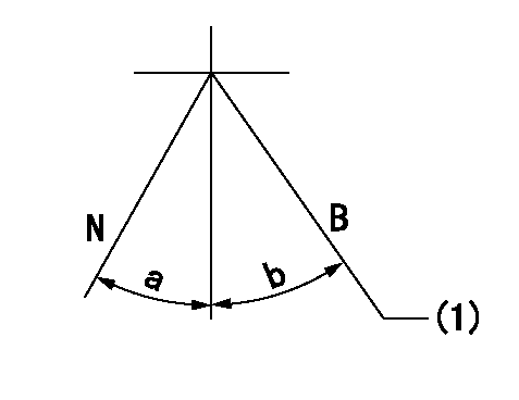
N:Normal
B:When boosted
(1)Rack position = aa at boost pressure 0.
----------
aa=11.5+-0.2mm
----------
a=(15deg) b=(8deg)
----------
aa=11.5+-0.2mm
----------
a=(15deg) b=(8deg)
Timing setting

(1)Pump vertical direction
(2)Coupling's key groove position at No 1 cylinder's beginning of injection
(3)B.T.D.C.: aa
(4)-
----------
aa=16deg
----------
a=(30deg)
----------
aa=16deg
----------
a=(30deg)
Information:
Rating Definitions
The Caterpillar marine propulsion engine rating definitions are:* A - Continuous Duty-For heavy duty use with little load cycling (throttle operation up to 100 percent of total time) in oceangoing displacement hulls such as freighters, tugboats and bottom-drag trawlers, and deep river towboats. Expected usage is 4000 hours per year or more.* B - Medium Duty-For use with full throttle operation up to 80 percent of total operation time with the balance of time below rated rpm in midwater trawlers, purse seiners, crew and supply boats, ferry boats with trips longer than one hour, and towboats in rivers where locks, sandbars, curves or traffic dictate frequent slowing. Expected usage is 4000 hours per year, average, is typical, but could be higher.* C - Intermittent Duty-For use with full throttle operation up to 50 percent of total operation time with the balance of time below rated rpm in yachts with displacement hulls, as well as ferries with trips less than one hour, fish boats moving at higher speeds out and back (e.g., lobster, crayfish and tuna), and short trip coastal freighters where engine load and speed are cyclical. Expected usage of up to 3000 hours per year, average, is typical.* D - Patrol Craft-For use in patrol, customs, police and some fire boats. Also for bow/stern thrusters. Full throttle operation up to ten percent of total operation time with balance of time below rated rpm. Expected usage is less than 2000 hours per year.* E - High Performance-For use in pleasure craft with planing hulls, as well as for pilot, harbor patrol and harbor master boats with full throttle operation up to five percent of total operation time with balance of time below rated rpm. Expected usage is 200 to 300 hours per year. Some fish boats operate on duty cycles where D or E engine ratings apply.Time at full throttle is the cumulative time the engine is operated at full throttle load and speed during a work cycle, duty cycle, or voyage.These rating definitions dictate the selection of a rating for an application based on a load profile determined by time at various throttle settings or engine speeds. In general, an application requiring less time at full throttle, or lower engine rpm at reduced throttle operation, can utilize a higher rating.Application Guidelines
In selecting a rating for a specific application, the most important consideration is time spent at full throttle. Additionally, these rating definitions identify percent of time at full throttle and corresponding times below rated rpm. This rpm reduction lowers kW (horsepower) requirements as propeller demand follows a cubic speed/power curve.For example, an engine operating at 90 percent of rated speed would be loaded by a typical propeller to about 73 percent of rated power. Operating at recommended reduced speed controls the engine load at or below the continuous power level.As a general guideline, typical operating parameters for each rating level are summarized in the following chart. For more information, refer to your Caterpillar dealer and EDS
