Information injection-pump assembly
ZEXEL
101605-3790
1016053790
KOMATSU
6138721930
6138721930

Rating:
Cross reference number
ZEXEL
101605-3790
1016053790
KOMATSU
6138721930
6138721930
Zexel num
Bosch num
Firm num
Name
101605-3790
6138721930 KOMATSU
INJECTION-PUMP ASSEMBLY
SA6D110 * K
SA6D110 * K
Calibration Data:
Adjustment conditions
Test oil
1404 Test oil ISO4113 or {SAEJ967d}
1404 Test oil ISO4113 or {SAEJ967d}
Test oil temperature
degC
40
40
45
Nozzle and nozzle holder
105780-8140
Bosch type code
EF8511/9A
Nozzle
105780-0000
Bosch type code
DN12SD12T
Nozzle holder
105780-2080
Bosch type code
EF8511/9
Opening pressure
MPa
17.2
Opening pressure
kgf/cm2
175
Injection pipe
Outer diameter - inner diameter - length (mm) mm 6-2-600
Outer diameter - inner diameter - length (mm) mm 6-2-600
Overflow valve opening pressure
kPa
157
123
191
Overflow valve opening pressure
kgf/cm2
1.6
1.25
1.95
Tester oil delivery pressure
kPa
157
157
157
Tester oil delivery pressure
kgf/cm2
1.6
1.6
1.6
Direction of rotation (viewed from drive side)
Right R
Right R
Injection timing adjustment
Direction of rotation (viewed from drive side)
Right R
Right R
Injection order
1-5-3-6-
2-4
Pre-stroke
mm
4
3.95
4.05
Beginning of injection position
Drive side NO.1
Drive side NO.1
Difference between angles 1
Cal 1-5 deg. 60 59.5 60.5
Cal 1-5 deg. 60 59.5 60.5
Difference between angles 2
Cal 1-3 deg. 120 119.5 120.5
Cal 1-3 deg. 120 119.5 120.5
Difference between angles 3
Cal 1-6 deg. 180 179.5 180.5
Cal 1-6 deg. 180 179.5 180.5
Difference between angles 4
Cyl.1-2 deg. 240 239.5 240.5
Cyl.1-2 deg. 240 239.5 240.5
Difference between angles 5
Cal 1-4 deg. 300 299.5 300.5
Cal 1-4 deg. 300 299.5 300.5
Injection quantity adjustment
Adjusting point
A
Rack position
9.6
Pump speed
r/min
900
900
900
Average injection quantity
mm3/st.
88.5
87.5
89.5
Max. variation between cylinders
%
0
-2
2
Basic
*
Fixing the rack
*
Injection quantity adjustment_02
Adjusting point
B
Rack position
7.3+-0.5
Pump speed
r/min
375
375
375
Average injection quantity
mm3/st.
13
13
13
Fixing the rack
*
Injection quantity adjustment_03
Adjusting point
C
Rack position
6.5+-0.5
Pump speed
r/min
930
930
930
Average injection quantity
mm3/st.
20
18.8
21.2
Max. variation between cylinders
%
0
-10
10
Fixing the rack
*
Test data Ex:
Governor adjustment
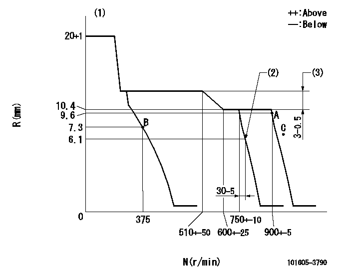
N:Pump speed
R:Rack position (mm)
(1)Target notch: K
(2)Idle sub spring setting: L1.
(3)Rack difference between N = N1 and N = N2
----------
K=16 L1=6.1-0.5mm N1=800r/min N2=400r/min
----------
----------
K=16 L1=6.1-0.5mm N1=800r/min N2=400r/min
----------
Speed control lever angle
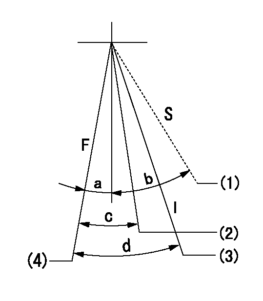
F:Full speed
I:Idle
S:Stop
(1)After confirming stopping, set at idling for delivery.
(2)Pump speed = aa
(3)Stopper bolt setting
(4)Speed = bb (at shipping)
----------
aa=750r/min bb=900r/min
----------
a=5deg+-5deg b=32deg+-3deg c=6deg+-5deg d=25deg+-5deg
----------
aa=750r/min bb=900r/min
----------
a=5deg+-5deg b=32deg+-3deg c=6deg+-5deg d=25deg+-5deg
Stop lever angle
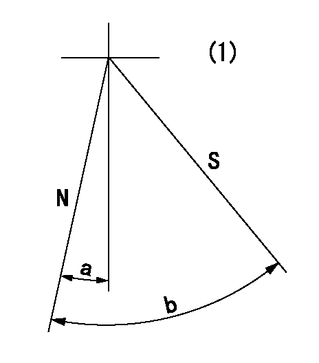
N:Pump normal
S:Stop the pump.
(1)No return spring
----------
----------
a=11.5deg+-5deg b=53deg+-5deg
----------
----------
a=11.5deg+-5deg b=53deg+-5deg
Timing setting

(1)Pump vertical direction
(2)Coupling's key groove position at No 1 cylinder's beginning of injection
(3)-
(4)-
----------
----------
a=(0deg)
----------
----------
a=(0deg)
Information:
Start By:a. remove timing gear cover
Do not disconnect the air line from the air compressor governor until the air pressure is zero.
1. Loosen the bleed valves, and release the air pressure in the air tank. 2. Disconnect the lines from air compressor (1), and remove the air compressor. 3. Remove sleeve (2) from air compressor drive gear (3). 4. Remove the nut and washer that holds the air compressor drive gear to the air compressor. Use tooling (A) to remove air compressor drive gear (3) from the air compressor. 5. Remove nuts (4) and plate (5). Remove gear assembly (6) from the shaft. 6. If damaged, remove bearing (7) from gear assembly (6) with tooling (B) and a press. 7. Remove three nuts (8) and the washers from the adapter assembly studs.
Typical Example8. Remove adapter assembly (9) from the timing gear plate. 9. Remove shaft (10), O-ring seal (11) and sleeve (12) from the adapter assembly.Install Air Compressor And Accessory Drive
1. Install sleeve (12) into the adapter assembly.2. Install shaft (10) and O-ring seal (11) on the adapter assembly. 3. Put adapter assembly (9) in position on the timing gear plate. Fasten it with the three nuts and washers. 4. Install the bearing in gear assembly (6) with tooling (A) and a press. Install the bearing until it is 1.5 0.5 mm (.06 .02 in.) below the surface of the gear as shown. 5. Put gear assembly (6) in position on the shaft.6. Put plate (5) in position, and install three nuts (4) to hold it. 7. Put air compressor drive gear (3) in position on the air compressor shaft, and install the washer and nut (13). Tighten the nut to a torque of 200 25 N m (150 18 lb.ft.). Tap the gear with a hammer and tighten nut (13) again to a torque of 200 25 N m (150 18 lb.ft.). 8. Install sleeve (2) on gear (3). 9. Put a gasket in position on air compressor (1) and install the air compressor on the timing cover plate.End By:a. install timing gear cover
Have questions with 101605-3790?
Group cross 101605-3790 ZEXEL
Komatsu
101605-3790
6138721930
INJECTION-PUMP ASSEMBLY
SA6D110
SA6D110