Information injection-pump assembly
BOSCH
9 400 615 353
9400615353
ZEXEL
101605-3720
1016053720
KOMATSU
6138721411
6138721411
Rating:
Service parts 101605-3720 INJECTION-PUMP ASSEMBLY:
1.
_
5.
AUTOM. ADVANCE MECHANIS
7.
COUPLING PLATE
8.
_
9.
_
11.
Nozzle and Holder
12.
Open Pre:MPa(Kqf/cm2)
24.5(250)
15.
NOZZLE SET
Include in #1:
101605-3720
as INJECTION-PUMP ASSEMBLY
Include in #2:
104746-1182
as _
Cross reference number
BOSCH
9 400 615 353
9400615353
ZEXEL
101605-3720
1016053720
KOMATSU
6138721411
6138721411
Zexel num
Bosch num
Firm num
Name
101605-3720
9 400 615 353
6138721411 KOMATSU
INJECTION-PUMP ASSEMBLY
S6D110 K
S6D110 K
Calibration Data:
Adjustment conditions
Test oil
1404 Test oil ISO4113 or {SAEJ967d}
1404 Test oil ISO4113 or {SAEJ967d}
Test oil temperature
degC
40
40
45
Nozzle and nozzle holder
105780-8140
Bosch type code
EF8511/9A
Nozzle
105780-0000
Bosch type code
DN12SD12T
Nozzle holder
105780-2080
Bosch type code
EF8511/9
Opening pressure
MPa
17.2
Opening pressure
kgf/cm2
175
Injection pipe
Outer diameter - inner diameter - length (mm) mm 6-2-600
Outer diameter - inner diameter - length (mm) mm 6-2-600
Tester oil delivery pressure
kPa
157
157
157
Tester oil delivery pressure
kgf/cm2
1.6
1.6
1.6
Direction of rotation (viewed from drive side)
Right R
Right R
Injection timing adjustment
Direction of rotation (viewed from drive side)
Right R
Right R
Injection order
1-5-3-6-
2-4
Pre-stroke
mm
4
3.95
4.05
Rack position
Point A R=A
Point A R=A
Beginning of injection position
Drive side NO.1
Drive side NO.1
Difference between angles 1
Cal 1-5 deg. 60 59.5 60.5
Cal 1-5 deg. 60 59.5 60.5
Difference between angles 2
Cal 1-3 deg. 120 119.5 120.5
Cal 1-3 deg. 120 119.5 120.5
Difference between angles 3
Cal 1-6 deg. 180 179.5 180.5
Cal 1-6 deg. 180 179.5 180.5
Difference between angles 4
Cyl.1-2 deg. 240 239.5 240.5
Cyl.1-2 deg. 240 239.5 240.5
Difference between angles 5
Cal 1-4 deg. 300 299.5 300.5
Cal 1-4 deg. 300 299.5 300.5
Injection quantity adjustment
Adjusting point
A
Rack position
9.9
Pump speed
r/min
1250
1250
1250
Average injection quantity
mm3/st.
71.3
70.3
72.3
Max. variation between cylinders
%
0
-2
2
Basic
*
Fixing the lever
*
Boost pressure
kPa
40
40
Boost pressure
mmHg
300
300
Injection quantity adjustment_02
Adjusting point
B
Rack position
7.5+-0.5
Pump speed
r/min
425
425
425
Average injection quantity
mm3/st.
11.2
10
12.4
Max. variation between cylinders
%
0
-10
10
Fixing the rack
*
Boost pressure
kPa
0
0
0
Boost pressure
mmHg
0
0
0
Boost compensator adjustment
Pump speed
r/min
400
400
400
Rack position
11.8
Boost pressure
kPa
13.3
9.3
17.3
Boost pressure
mmHg
100
70
130
Boost compensator adjustment_02
Pump speed
r/min
400
400
400
Rack position
12.3
Boost pressure
kPa
26.7
26.7
26.7
Boost pressure
mmHg
200
200
200
Test data Ex:
Governor adjustment
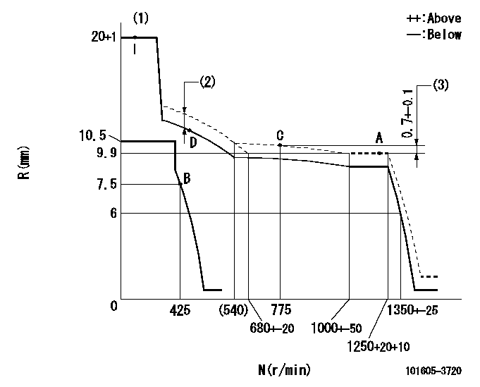
N:Pump speed
R:Rack position (mm)
(1)Target notch: K
(2)Boost compensator stroke: BCL
(3)Rack difference between N = N1 and N = N2
----------
K=18 BCL=0.5+-0.1mm N1=1250r/min N2=775r/min
----------
----------
K=18 BCL=0.5+-0.1mm N1=1250r/min N2=775r/min
----------
Speed control lever angle
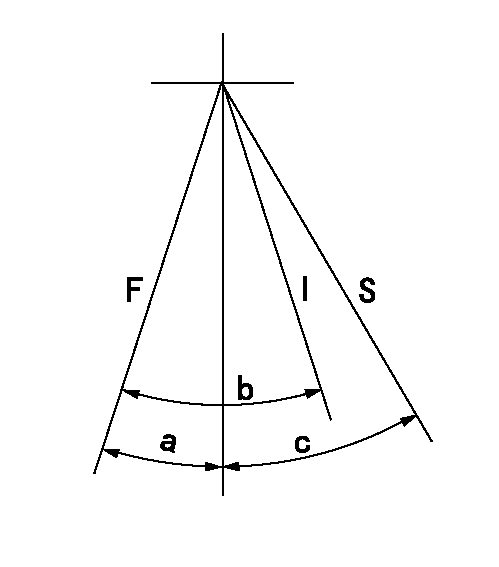
F:Full speed
I:Idle
S:Stop
----------
----------
a=18deg+-5deg b=29deg+-5deg c=32deg+-3deg
----------
----------
a=18deg+-5deg b=29deg+-5deg c=32deg+-3deg
Timing setting

(1)Pump vertical direction
(2)Coupling's key groove position at No 1 cylinder's beginning of injection
(3)-
(4)-
----------
----------
a=(0deg)
----------
----------
a=(0deg)
Information:
Start By:a. remove oil pump1. Check the main bearing caps for identification for their location and direction in the block. The caps must be installed in the same location and direction from which they were removed. 2. Remove No. 2 through No. 6 bearing caps (1). Remove thrust plates from the No. 4 main bearing.
If the crankshaft is turned in the wrong direction, the tab of the bearing will be pushed between the crankshaft and cylinder block. This can cause damage to either the crankshaft or cylinder block or both.
3. Remove the upper halves of the main bearings by putting tool (A) in oil hole (2) in the crankshaft. Turn the crankshaft in the direction which will push the end of the bearing with a tab out first.4. Remove the lower halves of the bearings from the caps. Install the bearings dry when the clearance checks are made. Put clean engine oil on the bearings for final assembly.5. Install the new bearings in the caps.6. Install the upper halves of the bearings in the cylinder block with tool (A). Be sure tabs (3) on the back of the bearings fit in the tab slots of the caps and cylinder block.The serviceman must be very careful to use Plastigage, tool (B) correctly. The following points must be remembered:... Make sure that the backs of the bearings and the bores are clean and dry.... Make sure that the bearing locking tabs are properly seated in their slots.... The crankshaft must be free of oil where the Plastigage touches it.... If the main bearing clearances are checked with the engine upright or on its side, the crankshaft must be supported. Use a jack under an adjacent crankshaft counterweight and hold the crankshaft against the crown of the bearing. If the crankshaft is not supported, the weight of the crankshaft will cause incorrect readings.... Put a piece of Plastigage on the crown of the bearing half that is in the cap. Do not allow the Plastigage to extend over the edge of the bearing.... Install the bearing cap using the correct torque-turn specifications. Do not use an impact wrench. Be careful not to dislodge the bearing when the cap is installed.... Do not turn the crankshaft with the Plastigage installed.... Carefully remove the cap but do not remove the Plastigage. Measure the width of the Plastigage while it is in the bearing cap or on the crankshaft journal. Do this by using the correct scale on the package. Record the measurements.... Remove the Plastigage before reinstalling the cap.When using Plastigage, the readings can sometimes be unclear. For example, all parts of the Plastigage are not the same width. Measure the major widths to make sure that they are within the specification range. Also, experience has shown that when checking clearances tighter than 0.10 mm (.004 in.) the readings may be low by 0.013 to 0.025 mm (.0005 to .0010 in.). Out-of-round journals can give faulty readings. Also, journal taper may be indicated
Have questions with 101605-3720?
Group cross 101605-3720 ZEXEL
Komatsu
101605-3720
9 400 615 353
6138721411
INJECTION-PUMP ASSEMBLY
S6D110
S6D110