Information injection-pump assembly
BOSCH
9 400 615 351
9400615351
ZEXEL
101605-3691
1016053691
KOMATSU
6136721491
6136721491
Rating:
Service parts 101605-3691 INJECTION-PUMP ASSEMBLY:
1.
_
5.
AUTOM. ADVANCE MECHANIS
7.
COUPLING PLATE
8.
_
9.
_
11.
Nozzle and Holder
6137-12-3200
12.
Open Pre:MPa(Kqf/cm2)
22.1{225}
15.
NOZZLE SET
Include in #1:
101605-3691
as INJECTION-PUMP ASSEMBLY
Include in #2:
104746-1191
as _
Cross reference number
BOSCH
9 400 615 351
9400615351
ZEXEL
101605-3691
1016053691
KOMATSU
6136721491
6136721491
Zexel num
Bosch num
Firm num
Name
101605-3691
9 400 615 351
6136721491 KOMATSU
INJECTION-PUMP ASSEMBLY
6D105 K
6D105 K
Calibration Data:
Adjustment conditions
Test oil
1404 Test oil ISO4113 or {SAEJ967d}
1404 Test oil ISO4113 or {SAEJ967d}
Test oil temperature
degC
40
40
45
Nozzle and nozzle holder
105780-8140
Bosch type code
EF8511/9A
Nozzle
105780-0000
Bosch type code
DN12SD12T
Nozzle holder
105780-2080
Bosch type code
EF8511/9
Opening pressure
MPa
17.2
Opening pressure
kgf/cm2
175
Injection pipe
Outer diameter - inner diameter - length (mm) mm 6-2-600
Outer diameter - inner diameter - length (mm) mm 6-2-600
Overflow valve
131424-3420
Overflow valve opening pressure
kPa
255
221
289
Overflow valve opening pressure
kgf/cm2
2.6
2.25
2.95
Tester oil delivery pressure
kPa
157
157
157
Tester oil delivery pressure
kgf/cm2
1.6
1.6
1.6
Direction of rotation (viewed from drive side)
Right R
Right R
Injection timing adjustment
Direction of rotation (viewed from drive side)
Right R
Right R
Injection order
1-5-3-6-
2-4
Pre-stroke
mm
3.3
3.25
3.35
Beginning of injection position
Drive side NO.1
Drive side NO.1
Difference between angles 1
Cal 1-5 deg. 60 59.5 60.5
Cal 1-5 deg. 60 59.5 60.5
Difference between angles 2
Cal 1-3 deg. 120 119.5 120.5
Cal 1-3 deg. 120 119.5 120.5
Difference between angles 3
Cal 1-6 deg. 180 179.5 180.5
Cal 1-6 deg. 180 179.5 180.5
Difference between angles 4
Cyl.1-2 deg. 240 239.5 240.5
Cyl.1-2 deg. 240 239.5 240.5
Difference between angles 5
Cal 1-4 deg. 300 299.5 300.5
Cal 1-4 deg. 300 299.5 300.5
Injection quantity adjustment
Adjusting point
A
Rack position
9
Pump speed
r/min
1175
1175
1175
Average injection quantity
mm3/st.
38
37
39
Max. variation between cylinders
%
0
-2
2
Basic
*
Fixing the lever
*
Injection quantity adjustment_02
Adjusting point
-
Rack position
8.4+-0.5
Pump speed
r/min
425
425
425
Average injection quantity
mm3/st.
9
8
10
Max. variation between cylinders
%
0
-10
10
Fixing the rack
*
Remarks
Adjust only variation between cylinders; adjust governor according to governor specifications.
Adjust only variation between cylinders; adjust governor according to governor specifications.
Test data Ex:
Governor adjustment
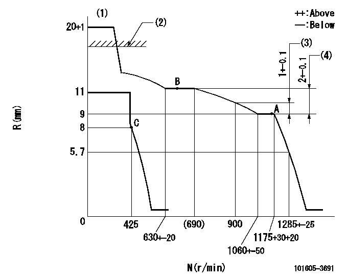
N:Pump speed
R:Rack position (mm)
(1)Target notch: K
(2)RACK LIMIT: RAL
(3)Rack difference between N = N1 and N = N2
(4)Rack difference between N = N3 and N = N4
----------
K=10 RAL=14.6+-0.2mm N1=1175r/min N2=900r/min N3=1175r/min N4=650r/min
----------
----------
K=10 RAL=14.6+-0.2mm N1=1175r/min N2=900r/min N3=1175r/min N4=650r/min
----------
Speed control lever angle
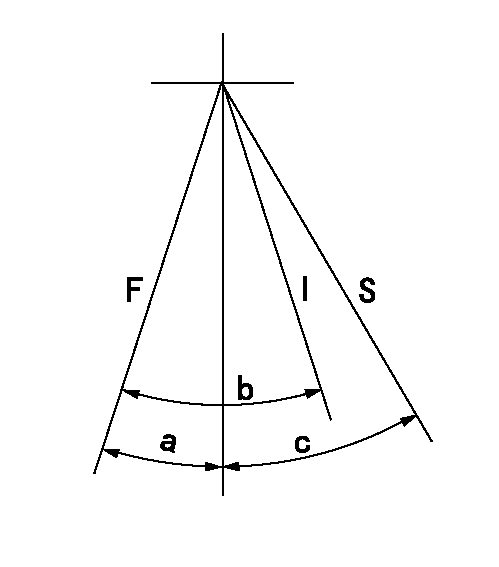
F:Full speed
I:Idle
S:Stop
----------
----------
a=7deg+-5deg b=19deg+-5deg c=32deg+-3deg
----------
----------
a=7deg+-5deg b=19deg+-5deg c=32deg+-3deg
Timing setting

(1)Pump vertical direction
(2)Coupling's key groove position at No 1 cylinder's beginning of injection
(3)-
(4)-
----------
----------
a=(0deg)
----------
----------
a=(0deg)
Information:
Start By:a. remove valve covers 1. Loosen the fuel injection line nut at the nozzle end with tool (A).2. Loosen the fuel line nut at the fuel injection line adapter with tool (B). Remove inner fuel injection lines (1). Install caps and plugs on all fuel line openings to keep dirt out of the fuel system. If necessary, use tooling (D) to turn the engine so the valves do not make contact with the pistons when the valves are opened with tool (C) to remove the push rods.3. Put compression on the valve springs with tool (C), and remove push rods (2). Put identification marks on the push rods as to their location in the engine.4. Push the push rod end of the rocker arms down. 5. Remove the intake valve lifter with tooling (E) as follows:a. Install 5P2685 Nut (3) and 5P6601 Collet (4) on 5P2408 Outer Handle Assembly (5).b. Install 5P6599 Inner Handle Assembly (6) in 5P2408 Outer Handle Assembly (5). c. Install tooling (E) in the intake valve lifter. Hold the 5P2408 Outer Handle Assembly, and tighten the 5P6599 Inner Handle Assembly until the 5P6601 Collet is tight against the inside of the intake valve lifter. d. Remove intake valve lifters (7) from the cylinder block with tooling (E). Put identification marks on the lifters as to their location in the engine. 6. Remove the exhaust valve lifters with tooling (E) as follows:a. Install 5P2685 Nut (3) and 5P6601 Collet (4) on 5P2408 Outer Handle Assembly (5). The opening in the cylinder head assembly for the intake valve lifter is larger than the opening in the exhaust valve lifter side. The tooling and each valve lifter must be installed and removed from the intake valve lifter side.b. Install the outer handle assembly in the intake valve lifter side of the cylinder head assembly. Slide the flat area of 5P2408 Outer Handle Assembly (5) through the head casting, and install the 5P6601 Collet in the exhaust valve lifters. c. Install 5P6599 Inner Handle Assembly (6) in 5P2408 Outer Handle Assembly (5). Hold the 5P2408 Handle Assembly, and tighten the 5P6599 Handle Assembly until the 5P6601 Collet is tight against the inside of the exhaust valve lifter.d. Pull the exhaust valve lifter up until the spring on the exhaust valve lifter is free from the cylinder block.e. Remove the 5P6599 Inner Handle Assembly. Slide the 5P2408 Outer Handle Assembly through the head casting, and remove it from the intake valve lifter side of the cylinder head. f. Use a magnet, and remove exhaust valve lifters (8) from the intake valve lifter side of the cylinder head assembly. Put identification marks on the lifters as to their location in the engine.7. Remove the guide springs from the lifters.Install Valve Lifters
Steps 1 and 2 must be done to install intake or exhaust valve lifters.
Make sure guide spring (9) is not damaged or worn. If the guide spring is damaged or worn, replace the guide spring. See Guideline For Reusable
Steps 1 and 2 must be done to install intake or exhaust valve lifters.
Make sure guide spring (9) is not damaged or worn. If the guide spring is damaged or worn, replace the guide spring. See Guideline For Reusable
Have questions with 101605-3691?
Group cross 101605-3691 ZEXEL
Komatsu
101605-3691
9 400 615 351
6136721491
INJECTION-PUMP ASSEMBLY
6D105
6D105