Information injection-pump assembly
BOSCH
9 400 615 348
9400615348
ZEXEL
101605-3621
1016053621
KOMATSU
6138721240
6138721240
Rating:
Service parts 101605-3621 INJECTION-PUMP ASSEMBLY:
1.
_
5.
AUTOM. ADVANCE MECHANIS
7.
COUPLING PLATE
8.
_
9.
_
11.
Nozzle and Holder
12.
Open Pre:MPa(Kqf/cm2)
24.5(250)

15.
NOZZLE SET
Include in #1:
101605-3621
as INJECTION-PUMP ASSEMBLY
Include in #2:
104746-1400
as _
Cross reference number
BOSCH
9 400 615 348
9400615348
ZEXEL
101605-3621
1016053621
KOMATSU
6138721240
6138721240
Zexel num
Bosch num
Firm num
Name
101605-3621
9 400 615 348
6138721240 KOMATSU
INJECTION-PUMP ASSEMBLY
S6D110 K 14BF INJECTION PUMP ASSY PE6AD PE
S6D110 K 14BF INJECTION PUMP ASSY PE6AD PE
Calibration Data:
Adjustment conditions
Test oil
1404 Test oil ISO4113 or {SAEJ967d}
1404 Test oil ISO4113 or {SAEJ967d}
Test oil temperature
degC
40
40
45
Nozzle and nozzle holder
105780-8140
Bosch type code
EF8511/9A
Nozzle
105780-0000
Bosch type code
DN12SD12T
Nozzle holder
105780-2080
Bosch type code
EF8511/9
Opening pressure
MPa
17.2
Opening pressure
kgf/cm2
175
Injection pipe
Outer diameter - inner diameter - length (mm) mm 6-2-600
Outer diameter - inner diameter - length (mm) mm 6-2-600
Tester oil delivery pressure
kPa
157
157
157
Tester oil delivery pressure
kgf/cm2
1.6
1.6
1.6
Direction of rotation (viewed from drive side)
Right R
Right R
Injection timing adjustment
Direction of rotation (viewed from drive side)
Right R
Right R
Injection order
1-5-3-6-
2-4
Pre-stroke
mm
4
3.95
4.05
Beginning of injection position
Drive side NO.1
Drive side NO.1
Difference between angles 1
Cal 1-5 deg. 60 59.5 60.5
Cal 1-5 deg. 60 59.5 60.5
Difference between angles 2
Cal 1-3 deg. 120 119.5 120.5
Cal 1-3 deg. 120 119.5 120.5
Difference between angles 3
Cal 1-6 deg. 180 179.5 180.5
Cal 1-6 deg. 180 179.5 180.5
Difference between angles 4
Cyl.1-2 deg. 240 239.5 240.5
Cyl.1-2 deg. 240 239.5 240.5
Difference between angles 5
Cal 1-4 deg. 300 299.5 300.5
Cal 1-4 deg. 300 299.5 300.5
Injection quantity adjustment
Adjusting point
A
Rack position
9.8
Pump speed
r/min
1050
1050
1050
Average injection quantity
mm3/st.
78.7
77.7
79.7
Max. variation between cylinders
%
0
-2
2
Basic
*
Fixing the lever
*
Injection quantity adjustment_02
Adjusting point
C
Rack position
8+-0.5
Pump speed
r/min
425
425
425
Average injection quantity
mm3/st.
13.1
11.9
14.3
Max. variation between cylinders
%
0
-10
10
Fixing the rack
*
Test data Ex:
Governor adjustment
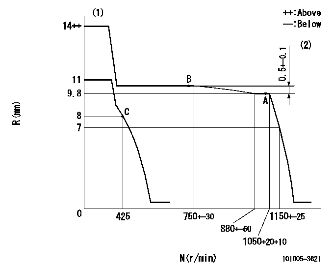
N:Pump speed
R:Rack position (mm)
(1)Target notch: K
(2)Rack difference between N = N1 and N = N2
----------
K=18 N1=1050r/min N2=700r/min
----------
----------
K=18 N1=1050r/min N2=700r/min
----------
Speed control lever angle
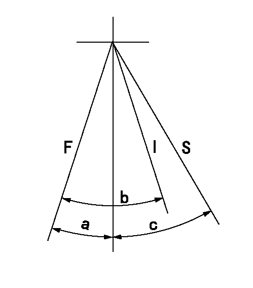
F:Full speed
I:Idle
S:Stop
----------
----------
a=16deg+-5deg b=26deg+-5deg c=32deg+-3deg
----------
----------
a=16deg+-5deg b=26deg+-5deg c=32deg+-3deg
Stop lever angle

N:Pump normal
S:Stop the pump.
----------
----------
a=10deg+-5deg b=53deg+-5deg
----------
----------
a=10deg+-5deg b=53deg+-5deg
Timing setting

(1)Pump vertical direction
(2)Coupling's key groove position at No 1 cylinder's beginning of injection
(3)-
(4)-
----------
----------
a=(0deg)
----------
----------
a=(0deg)
Information:
1. Remove nuts (1), cover (2), and the gasket. 2. Put No. 1 piston at the top center compression position (TDC) with the following procedure:a. Remove plug (3), two bolts and cover (2) from the flywheel housing. b. Install tool (B) in the flywheel housing. Use tool (B) to slowly rotate the engine in the direction of normal rotation, (counterclockwise as seen from the flywheel end of the engine), until timing bolt (4) can be installed in the flywheel housing and into the hole in the flywheel. c. Remove the valve cover from the valve cover base. Check to see if both rocker arms (5) for the No. 1 cylinder can be moved backward and forward. The No. 1 piston is at the top center compression position (TDC) when the timing bolt is installed in the flywheel and both rocker arms for the No. 1 cylinder can be moved backward and forward. If both rocker arms cannot be moved, the No. 1 piston is not at the top center compression position (TDC). Remove the timing bolt from the flywheel and rotate the engine in the direction of normal rotation, (counterclockwise as seen from the flywheel end of the engine one full turn 360°, and install the timing bolt again.3. Remove the timing bolt, and use tool (B) to rotate the engine in the opposite direction of normal rotation (clockwise as seen from the flywheel end of the engine) a minimum of 30°. The timing is correct if tool (A) and the timing bolt can be installed at the same time. The timing procedure in the Testing and Adjustment Manual must be done again if the timing bolt and tool (A) can not be installed at the same time.4. Remove the plug from the timing pin hole in the fuel injection pump housing, and install tool (A) in the timing pin hole. 5. Remove eight bolts (6) and automatic timing advance (7). 6. Remove gear (9) from fuel injection pump camshaft (8).The following steps are for the installation procedure.7. Install gear (9) on fuel injection pump camshaft (8). 8. Install two 3/8 in. - 16 NC × 6 in. (152.4 mm) long guide bolts (10). Space the guide bolts evenly.
There is a light spring located beneath the flyweight cover (12). Hold cover (12) while removing last nut (11). Slowly remove flyweight cover (12) to avoid dropping the spring.
9. Remove four nuts (11) and remove flyweight cover (12). 10. Put automatic timing advance (13) in position on the fuel injection pump camshaft, and install four bolts (14). Tighten bolts (14) just past finger tight. Remove guide bolts (15). 11. Install four nuts (16) standard torque. Install tool (C). 12. Tighten four knurled nuts (17) finger tight.
Do not use any tools to tighten the knurled nuts.
13. Install all mounting bolts (14) and tighten to a torque of 3 N m (27 lb.in.).14. Loosen knurled nuts (17). Remove four nuts (16) and remove tool (C).15. Install the spring and flyweight cover
Have questions with 101605-3621?
Group cross 101605-3621 ZEXEL
Komatsu
101605-3621
9 400 615 348
6138721240
INJECTION-PUMP ASSEMBLY
S6D110
S6D110