Information injection-pump assembly
ZEXEL
101605-3300
1016053300
KOMATSU
6137721170
6137721170

Rating:
Cross reference number
ZEXEL
101605-3300
1016053300
KOMATSU
6137721170
6137721170
Zexel num
Bosch num
Firm num
Name
Calibration Data:
Adjustment conditions
Test oil
1404 Test oil ISO4113 or {SAEJ967d}
1404 Test oil ISO4113 or {SAEJ967d}
Test oil temperature
degC
40
40
45
Nozzle and nozzle holder
105780-8140
Bosch type code
EF8511/9A
Nozzle
105780-0000
Bosch type code
DN12SD12T
Nozzle holder
105780-2080
Bosch type code
EF8511/9
Opening pressure
MPa
17.2
Opening pressure
kgf/cm2
175
Injection pipe
Outer diameter - inner diameter - length (mm) mm 6-2-600
Outer diameter - inner diameter - length (mm) mm 6-2-600
Tester oil delivery pressure
kPa
157
157
157
Tester oil delivery pressure
kgf/cm2
1.6
1.6
1.6
Direction of rotation (viewed from drive side)
Right R
Right R
Injection timing adjustment
Direction of rotation (viewed from drive side)
Right R
Right R
Injection order
1-5-3-6-
2-4
Pre-stroke
mm
3.3
3.25
3.35
Beginning of injection position
Drive side NO.1
Drive side NO.1
Difference between angles 1
Cal 1-5 deg. 60 59.5 60.5
Cal 1-5 deg. 60 59.5 60.5
Difference between angles 2
Cal 1-3 deg. 120 119.5 120.5
Cal 1-3 deg. 120 119.5 120.5
Difference between angles 3
Cal 1-6 deg. 180 179.5 180.5
Cal 1-6 deg. 180 179.5 180.5
Difference between angles 4
Cyl.1-2 deg. 240 239.5 240.5
Cyl.1-2 deg. 240 239.5 240.5
Difference between angles 5
Cal 1-4 deg. 300 299.5 300.5
Cal 1-4 deg. 300 299.5 300.5
Injection quantity adjustment
Adjusting point
A
Rack position
10.5
Pump speed
r/min
1150
1150
1150
Average injection quantity
mm3/st.
70.5
69.5
71.5
Max. variation between cylinders
%
0
-2
2
Basic
*
Fixing the lever
*
Boost pressure
kPa
64
64
Boost pressure
mmHg
480
480
Injection quantity adjustment_02
Adjusting point
B
Rack position
8+-0.5
Pump speed
r/min
365
365
365
Average injection quantity
mm3/st.
9.6
8.1
11.1
Max. variation between cylinders
%
0
-10
10
Fixing the rack
*
Boost pressure
kPa
0
0
0
Boost pressure
mmHg
0
0
0
Boost compensator adjustment
Pump speed
r/min
750
750
750
Rack position
10.5
Boost pressure
kPa
28
25.3
30.7
Boost pressure
mmHg
210
190
230
Boost compensator adjustment_02
Pump speed
r/min
750
750
750
Rack position
11.5
Boost pressure
kPa
50.7
44
57.4
Boost pressure
mmHg
380
330
430
Test data Ex:
Governor adjustment
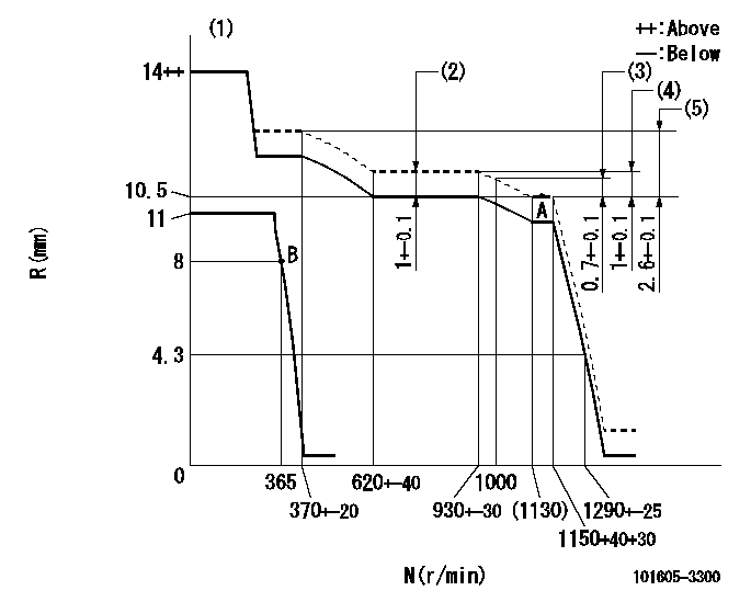
N:Pump speed
R:Rack position (mm)
(1)Target notch: K
(2)Boost compensator stroke
(3)Rack difference between N = N1 and N = N2
(4)Rack difference between N = N3 and N = N4
(5)Rack difference between N = N5 and N = N6.
----------
K=10 N1=1150r/min N2=1000r/min N3=1150r/min N4=800r/min N5=1150r/min N6=350r/min
----------
----------
K=10 N1=1150r/min N2=1000r/min N3=1150r/min N4=800r/min N5=1150r/min N6=350r/min
----------
Speed control lever angle
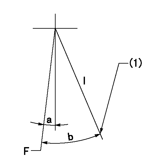
F:Full speed
I:Idle
(1)Stopper bolt setting
----------
----------
a=9deg+-5deg b=27deg+-5deg
----------
----------
a=9deg+-5deg b=27deg+-5deg
Stop lever angle
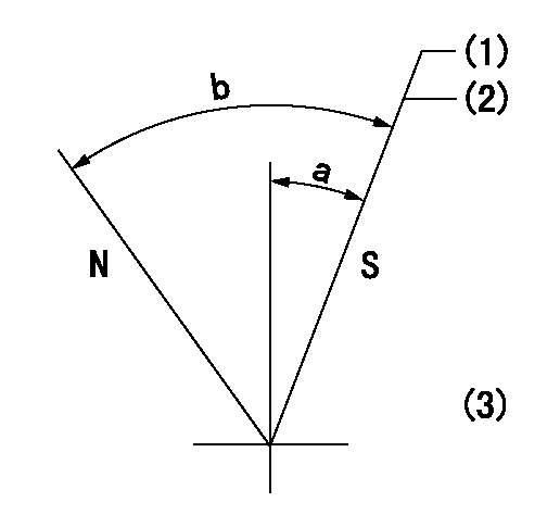
N:Pump normal
S:Stop the pump.
(1)At shipping
(2)Pump speed aa, rack position bb
(3)Stopper bolt setting
----------
aa=0r/min bb=1-0.2mm
----------
a=21deg+-5deg b=(55deg)
----------
aa=0r/min bb=1-0.2mm
----------
a=21deg+-5deg b=(55deg)
Timing setting

(1)Pump vertical direction
(2)Coupling's key groove position at No 1 cylinder's beginning of injection
(3)-
(4)-
----------
----------
a=(0deg)
----------
----------
a=(0deg)
Information:
Start By:a. remove engine
Keep all parts clean from contaminants. Contaminants put into the system may cause rapid wear and shortened component life.
1. Unplug the connector and remove speed pickup (1) to prevent damage to the unit.2. Install tool (A) on the flywheel as shown and fasten a hoist.3. Remove bolts (2) and flywheel (3). The weight of the flywheel is 72 kg (160 lb.).4. If necessary, remove the ring gear from the flywheel with a hammer and punch. The following steps are for the installation of the flywheel.
The ring gear must be installed with the chamfered side of the teeth up as shown in the inset of illustration A89844P2. This will put the chamfered side of the gear teeth toward the starter when the flywheel is installed so the starter will engage correctly.
1. Heat ring gear (4) to a maximum temperature of 320° C (608° F). Install the ring gear. 2. Install tooling (A) on the flywheel in the same position it was during removal. Install two 5/8" - 18 NF guide bolts in the crankshaft if necessary.3. Make an alignment of timing mark (5) on the crankshaft and timing mark (6) on the flywheel. Hold flywheel (3) in position and install bolts (2). Tighten bolts (2) to a torque of 205 27 N m (151 20 lb ft).4. Remove tool (A).5. Install speed pickup (1). Hand tighten speed pickup (1) until it makes contact with the flywheel. Loosen speed pickup (1) one half turn (180°) after contacting the flywheel. Tighten the locknut on speed pickup (1) and the connect wiring harness.End By:a. install engine