Information injection-pump assembly
BOSCH
9 400 613 257
9400613257
ZEXEL
101605-0300
1016050300
ISUZU
1156034860
1156034860
Rating:
Compare Prices: .
As an associate, we earn commssions on qualifying purchases through the links below

Fuel Injection Pump Compatible with Isuzu 6BG1T 6HK1 Engine XYo 101605-0300 15603486-0 115603-4860
EWAIDI Part Number:101605-0300 15603486-0 115603-4860 || Application:Compatible for Isuzu Engine 6HK1 6BG1T || The Fuel Injection Pump is a vital part of the vehicle's fuel system, delivering fuel to the engine for combustion. It pressurizes fuel from the tank and injects it into the cylinders for optimal efficiency and performance. Common in diesel engines, it is crucial for smooth and reliable operation. Regular maintenance is key to prevent engine problems and ensure optimal fuel consumption. || Note that the application information presented serves as a guide. It is advised to verify the part number and conduct a comparison with the existing parts prior to making a purchase. Should you have any inquiries, do not hesitate to reach out to us. || Great Value- This item offers consistent performance, excellent reliability, simple installation, and quick response time.
EWAIDI Part Number:101605-0300 15603486-0 115603-4860 || Application:Compatible for Isuzu Engine 6HK1 6BG1T || The Fuel Injection Pump is a vital part of the vehicle's fuel system, delivering fuel to the engine for combustion. It pressurizes fuel from the tank and injects it into the cylinders for optimal efficiency and performance. Common in diesel engines, it is crucial for smooth and reliable operation. Regular maintenance is key to prevent engine problems and ensure optimal fuel consumption. || Note that the application information presented serves as a guide. It is advised to verify the part number and conduct a comparison with the existing parts prior to making a purchase. Should you have any inquiries, do not hesitate to reach out to us. || Great Value- This item offers consistent performance, excellent reliability, simple installation, and quick response time.

Fits Compatible with Isuzu Engine 6HK1 6HK1T 6BG1 6BG1T Fuel Injection Pump 15603486-0 101605-0300 115603-4860
EWAIDI Part Number: 15603486-0 101605-0300 115603-4860 Note: Please check the fitment carefully before purchase. Or just tell us the part number you need. || Part Name: Fuel Injection Pump || Engine Model 6BG1T is a renowned diesel engine favored for its power, efficiency, and durability in heavy-duty vehicles, construction equipment, and marine use. With a 6.494 liter displacement and turbocharger, it offers strong torque and horsepower while meeting strict emissions standards. Known for its reliability and longevity, it is a top choice for industrial and commercial needs worldwide. || Suitable for use with Isuzu engines 6HK1, 6HK1T, 6BG1, and 6BG1T. || Included in the package is one piece of the Fuel Injection Pump with the part numbers 15603486-0, 101605-0300, and 115603-4860.
EWAIDI Part Number: 15603486-0 101605-0300 115603-4860 Note: Please check the fitment carefully before purchase. Or just tell us the part number you need. || Part Name: Fuel Injection Pump || Engine Model 6BG1T is a renowned diesel engine favored for its power, efficiency, and durability in heavy-duty vehicles, construction equipment, and marine use. With a 6.494 liter displacement and turbocharger, it offers strong torque and horsepower while meeting strict emissions standards. Known for its reliability and longevity, it is a top choice for industrial and commercial needs worldwide. || Suitable for use with Isuzu engines 6HK1, 6HK1T, 6BG1, and 6BG1T. || Included in the package is one piece of the Fuel Injection Pump with the part numbers 15603486-0, 101605-0300, and 115603-4860.
Compatible with Isuzu Engine 6HK1 6HK1T 6BG1 6BG1T Fuel Injection Pump 15603486-0 101605-0300 115603-4860
EWAIDI Part Number: 15603486-0 101605-0300 115603-4860 Note: Please check the fitment carefully before purchase. Or just tell us the part number you need. || Part Name: Fuel Injection Pump || This product is designed to be compatible with Isuzu Engine models 6HK1, 6HK1T, 6BG1, and 6BG1T. It is suitable for use with these specific engine types and is designed to work effectively with them. || Included in the package is one piece of the Fuel Injection Pump with the part numbers 15603486-0, 101605-0300, and 115603-4860.
EWAIDI Part Number: 15603486-0 101605-0300 115603-4860 Note: Please check the fitment carefully before purchase. Or just tell us the part number you need. || Part Name: Fuel Injection Pump || This product is designed to be compatible with Isuzu Engine models 6HK1, 6HK1T, 6BG1, and 6BG1T. It is suitable for use with these specific engine types and is designed to work effectively with them. || Included in the package is one piece of the Fuel Injection Pump with the part numbers 15603486-0, 101605-0300, and 115603-4860.
You can express buy:

USD 2005.01
19-05-2025
19-05-2025
6BG1T Fuel Pump For ZX240 ZX230 ZX220 ZX200 1-15603049-0 1-15603486-0 1-15603378-2 1-15603395-0 1-15603396-0
USD 2944.38
27-05-2025
27-05-2025
EX200-5 ZX200 ZX225 Excavator 6bg1 6bg1t Diesel Engine Fuel Pump 1156034860 Injection Oil Pump 1156033950 for HITACHI ZEXEL
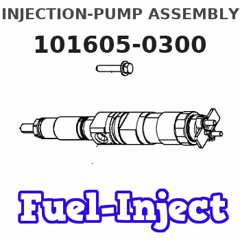
Service parts 101605-0300 INJECTION-PUMP ASSEMBLY:
1.
_

5.
AUTOM. ADVANCE MECHANIS
6.
COUPLING PLATE
8.
_
9.
_
11.
Nozzle and Holder
1-15300-394-0
12.
Open Pre:MPa(Kqf/cm2)
18.1{185}
 Fuel Injector Nozzle DLLA150SM303 105025-3030")
15.
NOZZLE SET
Cross reference number
Zexel num
Bosch num
Firm num
Name
101605-0300
9 400 613 257
1156034860 ISUZU
INJECTION-PUMP ASSEMBLY
6BG1-T K 14BF INJECTION PUMP ASSY PE6AD PE
6BG1-T K 14BF INJECTION PUMP ASSY PE6AD PE
Information:
Start By:a. remove shutoff solenoidb. remove governorc. remove governor spring groupd. remove rear cover group 1. Remove riser (1). 2. Remove retaining ring (2), races (3) with bearing (4) and shims (5). 3. Remove four flyweight bolts (6) with washers.4. Remove flyweights (7), toe (8) and pins (9). Keep parts of each flyweight group together.5. Remove pin (9). Inspect for wear.6. Remove flyweight toe (8). Inspect for wear.7. Inspect flyweight pin bore for wear. Replace any flyweight parts with wear.8. Hold flyweight carrier (10) to keep from rotating, and remove eight carrier bolts (11). Replace, do not reuse, eight carrier bolts (11),9. Remove flyweight carrier (10), riser shaft (12) and the drive pin.10. Remove fuel transfer pump (13) and the fittings. See the topic, Remove Fuel Transfer Pump.11. Remove two bolts (14) and remove shutoff assembly (15). 12. If necessary, remove levers (16), (17) and remove spring (18). These components are part of the shutoff assembly service replacement. Do not disassemble shutoff assembly beyond this point. 13. Remove throttle spring (23), setscrew (19), spring (20) and lever (21).14. Remove retaining ring (22) and pull throttle shaft assembly (24) out of the housing bore. Do not disassemble throttle shaft assembly beyond this point.15. If necessary, remove the throttle shaft seal.16. Remove governor front housing from Repair Stand, and turn it over. If not previously removed, remove the housing o-ring seal. 17. Remove drive gear bolt (25) and lift cover (26) from the gear drive unit.
Be careful not to damage the "C" spring, by over compressing with the vise.
18. Use a vise to remove "C" (27). Remove gear assembly (28). Do not disassemble the gear beyond this point
Do not attempt to remove the gear carrier, it is serviced as part of the housing assembly.
The following steps are for the assembly of the front housing.19. Position gear (28) onto carrier (29). Assemble with short length, 8.43 mm (.332 in.), of dowel pin in gear assembly, face down (toward housing). Be sure gear rotates freely on carrier bore.
Be careful not to damage the "C" spring, by over compressing with the vise.
20. Install "C" spring (27). Be sure that there is preload when assembled. Orient cover so the dowel, which is pressed into carrier (29), fits into the hole in the cover. The dowel from the gear assembly fits into the slot in the cover.21. Install cover (26) and bolt (25).22. Mount front housing to repair stand.23. If the throttle shaft seal was removed, install it with the lip toward the inside of the governor.24. Install throttle shaft (24) into housing bore, and install retaining ring (22).25. Slide lever (21) and spring (20) onto throttle shaft. The long leg of spring (20) fits into slot on lever (21). The other end of spring (20) fits into slot on the throttle shaft.26. Install throttle spring (23). These parts must be oriented correctly for proper governor operation. Following is a quick check for proper assembly.27. With zero preload on spring, the threaded hole in throttle
Be careful not to damage the "C" spring, by over compressing with the vise.
18. Use a vise to remove "C" (27). Remove gear assembly (28). Do not disassemble the gear beyond this point
Do not attempt to remove the gear carrier, it is serviced as part of the housing assembly.
The following steps are for the assembly of the front housing.19. Position gear (28) onto carrier (29). Assemble with short length, 8.43 mm (.332 in.), of dowel pin in gear assembly, face down (toward housing). Be sure gear rotates freely on carrier bore.
Be careful not to damage the "C" spring, by over compressing with the vise.
20. Install "C" spring (27). Be sure that there is preload when assembled. Orient cover so the dowel, which is pressed into carrier (29), fits into the hole in the cover. The dowel from the gear assembly fits into the slot in the cover.21. Install cover (26) and bolt (25).22. Mount front housing to repair stand.23. If the throttle shaft seal was removed, install it with the lip toward the inside of the governor.24. Install throttle shaft (24) into housing bore, and install retaining ring (22).25. Slide lever (21) and spring (20) onto throttle shaft. The long leg of spring (20) fits into slot on lever (21). The other end of spring (20) fits into slot on the throttle shaft.26. Install throttle spring (23). These parts must be oriented correctly for proper governor operation. Following is a quick check for proper assembly.27. With zero preload on spring, the threaded hole in throttle
Have questions with 101605-0300?
Group cross 101605-0300 ZEXEL
Isuzu
101605-0300
9 400 613 257
1156034860
INJECTION-PUMP ASSEMBLY
6BG1-T
6BG1-T