Information injection-pump assembly
BOSCH
9 400 612 366
9400612366
ZEXEL
101605-0160
1016050160
ISUZU
1156034270
1156034270

Rating:
Service parts 101605-0160 INJECTION-PUMP ASSEMBLY:
1.
_
5.
AUTOM. ADVANCE MECHANIS
6.
COUPLING PLATE
8.
_
9.
_
11.
Nozzle and Holder
1-15300-421-0
12.
Open Pre:MPa(Kqf/cm2)
18.1{185}
15.
NOZZLE SET
Include in #1:
101605-0160
as INJECTION-PUMP ASSEMBLY
Include in #2:
104746-1002
as _
Cross reference number
BOSCH
9 400 612 366
9400612366
ZEXEL
101605-0160
1016050160
ISUZU
1156034270
1156034270
Zexel num
Bosch num
Firm num
Name
Calibration Data:
Adjustment conditions
Test oil
1404 Test oil ISO4113 or {SAEJ967d}
1404 Test oil ISO4113 or {SAEJ967d}
Test oil temperature
degC
40
40
45
Nozzle and nozzle holder
105780-8140
Bosch type code
EF8511/9A
Nozzle
105780-0000
Bosch type code
DN12SD12T
Nozzle holder
105780-2080
Bosch type code
EF8511/9
Opening pressure
MPa
17.2
Opening pressure
kgf/cm2
175
Injection pipe
Outer diameter - inner diameter - length (mm) mm 6-2-600
Outer diameter - inner diameter - length (mm) mm 6-2-600
Overflow valve
134424-4120
Overflow valve opening pressure
kPa
255
221
289
Overflow valve opening pressure
kgf/cm2
2.6
2.25
2.95
Tester oil delivery pressure
kPa
255
255
255
Tester oil delivery pressure
kgf/cm2
2.6
2.6
2.6
RED4 control unit part number
407915-0
590
RED4 rack sensor specifications
mm
19
Direction of rotation (viewed from drive side)
Right R
Right R
Injection timing adjustment
Direction of rotation (viewed from drive side)
Right R
Right R
Injection order
1-5-3-6-
2-4
Pre-stroke
mm
4.2
4.15
4.25
Beginning of injection position
Drive side NO.1
Drive side NO.1
Difference between angles 1
Cal 1-5 deg. 60 59.5 60.5
Cal 1-5 deg. 60 59.5 60.5
Difference between angles 2
Cal 1-3 deg. 120 119.5 120.5
Cal 1-3 deg. 120 119.5 120.5
Difference between angles 3
Cal 1-6 deg. 180 179.5 180.5
Cal 1-6 deg. 180 179.5 180.5
Difference between angles 4
Cyl.1-2 deg. 240 239.5 240.5
Cyl.1-2 deg. 240 239.5 240.5
Difference between angles 5
Cal 1-4 deg. 300 299.5 300.5
Cal 1-4 deg. 300 299.5 300.5
Injection quantity adjustment
Rack position
(10)
PWM
%
44.4
Pump speed
r/min
1100
1100
1100
Average injection quantity
mm3/st.
100
98.5
101.5
Max. variation between cylinders
%
0
-2
2
Basic
*
Injection quantity adjustment_02
Rack position
(7.2)
PWM
%
28.9+-2.
8
Pump speed
r/min
450
450
450
Average injection quantity
mm3/st.
14.5
13.2
15.8
Max. variation between cylinders
%
0
-14
14
Injection quantity adjustment_03
Rack position
-
PWM
%
-
Pump speed
r/min
100
100
100
Average injection quantity
mm3/st.
105
100
110
Rack limit
*
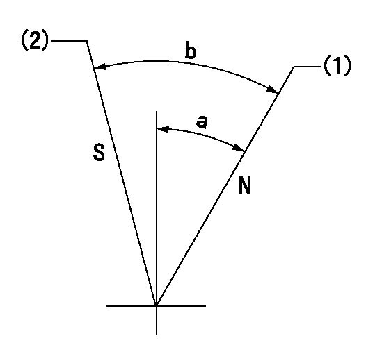
Test data Ex:
Speed control lever angle

N:Pump normal
S:Stop the pump.
(1)Rack position = aa
(2)Rack position bb
----------
aa=20mm bb=1mm
----------
a=27deg+-5deg b=37deg+-5deg
----------
aa=20mm bb=1mm
----------
a=27deg+-5deg b=37deg+-5deg
0000000901

(1)Pump vertical direction
(2)Position of gear mark 'CC' at No 1 cylinder's beginning of injection
(3)B.T.D.C.: aa
(4)-
----------
aa=9deg
----------
a=(100deg)
----------
aa=9deg
----------
a=(100deg)
Stop lever angle

(PWM) Pulse width modulation (%)
(R) Rack position (mm)
Rack sensor output characteristics
1. Rack limit adjustment
(1)Measure the rack position R2 for PWM a2%.
(2)Confirm that it is within the range R2 = 15+-1 mm.
(3)Measure the rack position R1 at PWM a %.
(4)Confirm that it is within the range R2 - R1 = 10+-0.1 mm.
2. Check the limp home operation.
(1)Move the switch box's limp home switch to the limp home side.
(2)Confirm rack position L1 (mm ) and L2 (mm) for PWM in the above table.
3. Check the pull down operation.
(1)Confirm that the rack position is 19 mm at PWM B%.
(2)In the conditions described in the above table, move the switch box's pull down switch to the pull down side and confirm that the rack position momentarily becomes 1 mm or less.
----------
a1=16.25% a2=72.5% L1=1--mm L2=19++mm A=5% B=95%
----------
----------
a1=16.25% a2=72.5% L1=1--mm L2=19++mm A=5% B=95%
----------
Information:
Start By:a. remove flywheel housingb. remove oil pan platec. remove camshaft
Keep all parts clean from contaminants. Contaminants put into the system may cause rapid wear and shortened component life.
1. Remove the camshaft bearings from the cylinder block with tooling (A). Start with the front bearing and work to the rear. The following steps are for the installation of the camshaft bearings.2. Use tooling (A) to install the camshaft bearings in the cylinder block. 3. Install the camshaft bearings in the cylinder block as follows:a. Install the front bearing to a depth of 0.5 0.5 mm (.02 .02 in) and with the oil holes in a horizontal position and the joint at the top of the engine. The joint can not be more than 15° from vertical in either direction.b. Install the remainder of the bearings. Install the bearings to the dimensions given from the front face of the cylinder block: A) 154.0 0.5 mm (6.06 .02 in), B) 303.2 0.5 mm (11.94 .02 in), C) 601.7 0.5 mm (23.69 .02 in), D) 903.4 0.5 mm (35.57 .02 in).End By:a. install camshaftb. install oil pan platec. install flywheel housing
Perform Scheduled Oil Sampling on oil wetted compartments after performing service work to check for contaminants left in the system following repair. Contaminants put into the system may cause rapid wear and shortened component life.
