Information injection-pump assembly
BOSCH
9 400 612 304
9400612304
ZEXEL
101605-0090
1016050090
ISUZU
1156033950
1156033950

Rating:
Compare Prices: .
As an associate, we earn commssions on qualifying purchases through the links below
Compatible with Isuzu ZAX200 ZX230 Engine 6BG1 6BG1T Fuel Injection Pump 101605-0090 1016050090
KoovDem Part Number: 101605-0090 1016050090 Note: Please check the fitment carefully before purchase. Or just tell us the part number you need. || Part Name: Fuel Injection Pump || The engine model is 6BG1. || Compatible with Isuzu ZAX200 and ZX230 models, this product is designed for 6BG1 and 6BG1T engines. It ensures seamless integration and optimal performance, making it the ideal choice for replacement or upgrades. Rest easy knowing your engine is in good hands with this reliable component. || Included in the package is one piece of the Fuel Injection Pump, with the part number 101605-0090 or 1016050090.
KoovDem Part Number: 101605-0090 1016050090 Note: Please check the fitment carefully before purchase. Or just tell us the part number you need. || Part Name: Fuel Injection Pump || The engine model is 6BG1. || Compatible with Isuzu ZAX200 and ZX230 models, this product is designed for 6BG1 and 6BG1T engines. It ensures seamless integration and optimal performance, making it the ideal choice for replacement or upgrades. Rest easy knowing your engine is in good hands with this reliable component. || Included in the package is one piece of the Fuel Injection Pump, with the part number 101605-0090 or 1016050090.
WZCNLXLX Fuel Injection Pump 1156033783 101605-0390 101605-0090 898175-9510 For Hitachi ZAX200 ZAX230 Excavator For Isuzu 6BG1 Engine
WZCNLXLX Item Name:Fuel Injection Pump || Item Number:1156033783 101605-0390 101605-0090 898175-9510 || Application: For Hitachi ZAX200 ZAX230 Excavator For Isuzu 6BG1 Engine || Note: If you are unsure if the product is suitable.In order not to delay your use of the parts, please provide your engine nameplate or serial number and part number, and we will help you confirm if it is suitable. To avoid unnecessary returns, please check the product image and part number to ensure it is the product you want. || Tip: Please contact us - we are a professional sales team and we have many products to offer to you. Many buyers are very satisfied with our service. You can get first-class products and high-quality services from us, believe me, you will have a pleasant shopping experience here.
WZCNLXLX Item Name:Fuel Injection Pump || Item Number:1156033783 101605-0390 101605-0090 898175-9510 || Application: For Hitachi ZAX200 ZAX230 Excavator For Isuzu 6BG1 Engine || Note: If you are unsure if the product is suitable.In order not to delay your use of the parts, please provide your engine nameplate or serial number and part number, and we will help you confirm if it is suitable. To avoid unnecessary returns, please check the product image and part number to ensure it is the product you want. || Tip: Please contact us - we are a professional sales team and we have many products to offer to you. Many buyers are very satisfied with our service. You can get first-class products and high-quality services from us, believe me, you will have a pleasant shopping experience here.
Compatible with Isuzu ZAX200 ZX230 Engine Fuel Injection Pump 101605-0090 1016050090 6BG1 6BG1T 101605-0090
KoovDem Part Number:3960901 3977327 || Part Name: Fuel Injection Pump || The 6CTA8.3 diesel engine is known for its durability and high performance, with an 8.3-liter displacement that delivers strong horsepower and torque while remaining fuel-efficient. It is widely used in agricultural machinery, construction equipment, and power generators, thanks to its robust design and advanced technology that ensures reliable operation in tough conditions. A top choice for those looking for superior performance and long-lasting durability in their equipment. || Engineered to work flawlessly with the 4BT and 4BT3.9 Cummins Engine models, this product seamlessly integrates for peak performance. Versatile and dependable, it is perfect for numerous industries, providing consistent operation. With guaranteed compatibility, users can trust in its reliable performance for any industrial, commercial, or recreational application. Trust in this product for top-notch performance with Cummins Engine models 4BT and 4BT3.9. || The package includes one set of Fuel Injection Pump, specifically the 3960901 and 3977327 models.
KoovDem Part Number:3960901 3977327 || Part Name: Fuel Injection Pump || The 6CTA8.3 diesel engine is known for its durability and high performance, with an 8.3-liter displacement that delivers strong horsepower and torque while remaining fuel-efficient. It is widely used in agricultural machinery, construction equipment, and power generators, thanks to its robust design and advanced technology that ensures reliable operation in tough conditions. A top choice for those looking for superior performance and long-lasting durability in their equipment. || Engineered to work flawlessly with the 4BT and 4BT3.9 Cummins Engine models, this product seamlessly integrates for peak performance. Versatile and dependable, it is perfect for numerous industries, providing consistent operation. With guaranteed compatibility, users can trust in its reliable performance for any industrial, commercial, or recreational application. Trust in this product for top-notch performance with Cummins Engine models 4BT and 4BT3.9. || The package includes one set of Fuel Injection Pump, specifically the 3960901 and 3977327 models.
You can express buy:
USD 1249.81
19-05-2025
19-05-2025
OEM Quality Isuzu 6BG1 6BG1T Engine Injecti on Pump Assembly 115603-3950 1-15603395-0 Injecti on Pump 101605-0090
Images:
USD 2944.38

[27-May-2025]
USD 2516.26

[19-May-2025]
USD 2843.25

[31-May-2025]
USD 2176.63

[07-Jan-2023]
Service parts 101605-0090 INJECTION-PUMP ASSEMBLY:
1.
_
5.
AUTOM. ADVANCE MECHANIS
6.
COUPLING PLATE
8.
_
9.
_
11.
Nozzle and Holder
1-15300-421-0
12.
Open Pre:MPa(Kqf/cm2)
18.1{185}
15.
NOZZLE SET
Cross reference number
BOSCH
9 400 612 304
9400612304
ZEXEL
101605-0090
1016050090
ISUZU
1156033950
1156033950
Zexel num
Bosch num
Firm num
Name
101605-0090
9 400 612 304
1156033950 ISUZU
INJECTION-PUMP ASSEMBLY
6BG1-T K 14BF INJECTION PUMP ASSY PE6AD PE
6BG1-T K 14BF INJECTION PUMP ASSY PE6AD PE
Calibration Data:
Adjustment conditions
Test oil
1404 Test oil ISO4113 or {SAEJ967d}
1404 Test oil ISO4113 or {SAEJ967d}
Test oil temperature
degC
40
40
45
Nozzle and nozzle holder
105780-8140
Bosch type code
EF8511/9A
Nozzle
105780-0000
Bosch type code
DN12SD12T
Nozzle holder
105780-2080
Bosch type code
EF8511/9
Opening pressure
MPa
17.2
Opening pressure
kgf/cm2
175
Injection pipe
Outer diameter - inner diameter - length (mm) mm 6-2-600
Outer diameter - inner diameter - length (mm) mm 6-2-600
Overflow valve
134424-4120
Overflow valve opening pressure
kPa
255
221
289
Overflow valve opening pressure
kgf/cm2
2.6
2.25
2.95
Tester oil delivery pressure
kPa
255
255
255
Tester oil delivery pressure
kgf/cm2
2.6
2.6
2.6
Direction of rotation (viewed from drive side)
Right R
Right R
Injection timing adjustment
Direction of rotation (viewed from drive side)
Right R
Right R
Injection order
1-5-3-6-
2-4
Pre-stroke
mm
4.2
4.15
4.25
Beginning of injection position
Drive side NO.1
Drive side NO.1
Difference between angles 1
Cal 1-5 deg. 60 59.5 60.5
Cal 1-5 deg. 60 59.5 60.5
Difference between angles 2
Cal 1-3 deg. 120 119.5 120.5
Cal 1-3 deg. 120 119.5 120.5
Difference between angles 3
Cal 1-6 deg. 180 179.5 180.5
Cal 1-6 deg. 180 179.5 180.5
Difference between angles 4
Cyl.1-2 deg. 240 239.5 240.5
Cyl.1-2 deg. 240 239.5 240.5
Difference between angles 5
Cal 1-4 deg. 300 299.5 300.5
Cal 1-4 deg. 300 299.5 300.5
Injection quantity adjustment
Adjusting point
A
Rack position
10.4
Pump speed
r/min
1050
1050
1050
Average injection quantity
mm3/st.
95
93.5
96.5
Max. variation between cylinders
%
0
-2
2
Basic
*
Fixing the lever
*
Injection quantity adjustment_02
Adjusting point
-
Rack position
7.7+-0.5
Pump speed
r/min
450
450
450
Average injection quantity
mm3/st.
12
10.7
13.3
Max. variation between cylinders
%
0
-14
14
Fixing the rack
*
Remarks
Adjust only variation between cylinders; adjust governor according to governor specifications.
Adjust only variation between cylinders; adjust governor according to governor specifications.
Injection quantity adjustment_03
Adjusting point
D
Rack position
10.6++
Pump speed
r/min
100
100
100
Average injection quantity
mm3/st.
105
100
110
Fixing the lever
*
Rack limit
*
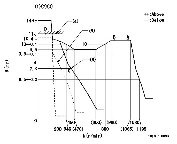
Test data Ex:
Governor adjustment

N:Pump speed
R:Rack position (mm)
(1)Target notch: K
(2)Tolerance for racks not indicated: +-0.05mm.
(3)Do not adjust boost compensator spring.
(4)RACK LIMIT
(5)Set idle sub-spring
(6)Main spring setting
----------
K=17
----------
----------
K=17
----------
Speed control lever angle

F:Full speed
I:Idle
(1)Stopper bolt setting
----------
----------
a=(2deg)+-5deg b=(18deg)+-5deg
----------
----------
a=(2deg)+-5deg b=(18deg)+-5deg
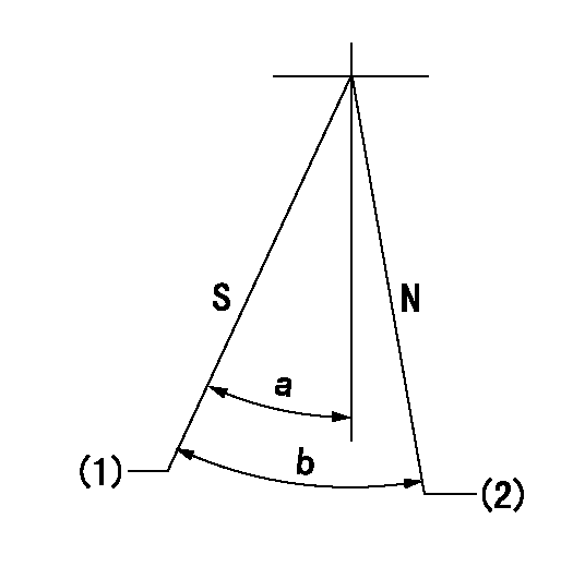
Stop lever angle

N:Pump normal
S:Stop the pump.
(1)Pump speed aa and rack position bb (to be sealed at delivery)
(2)Normal
----------
aa=0r/min bb=1-0.5mm
----------
a=50deg+-5deg b=(55deg)
----------
aa=0r/min bb=1-0.5mm
----------
a=50deg+-5deg b=(55deg)
0000001501 TAMPER PROOF

Tamperproofing-equipped boost compensator cover installation procedure
(A) After adjusting the boost compensator, tighten the bolts to remove the heads.
(1)Before adjusting the governor and the boost compensator, tighten the screw to the specified torque.
(Tightening torque T = T1 maximum)
(2)After adjusting the governor and the boost compensator, tighten to the specified torque to break off the bolt heads.
(Tightening torque T = T2)
----------
T1=2.5N-m(0.25kgf-m) T2=2.9~4.4N-m(0.3~0.45kgf-m)
----------
----------
T1=2.5N-m(0.25kgf-m) T2=2.9~4.4N-m(0.3~0.45kgf-m)
----------
Timing setting

(1)Pump vertical direction
(2)Position of gear mark 'CC' at No 1 cylinder's beginning of injection
(3)B.T.D.C.: aa
(4)-
----------
aa=9deg
----------
a=(100deg)
----------
aa=9deg
----------
a=(100deg)
Information:
Start By:a. remove crankshaft vibration damper and pulley
Keep all parts clean from contaminants. Contaminants put into the system may cause rapid wear and shortened component life.
When replacement of the front seal is made, a replacement of the wear sleeve must also be made.
1. Remove the two bolts, washers, clamp (1), retainer (2) and the O-ring seal.2. Use tool (A) and a press to remove seal (3).3. Install the O-ring seal, retainer (2) and the two bolts, washers, and clamp (1). 4. Install tool (C) in the bore of retainer (2) as shown.5. Install tool (B) between tool (C) and the wear sleeve. Turn tool (B) with a wrench until the edge of the tool makes a flat place (crease) in the wear sleeve. Do this in two or more places until the wear sleeve is loose.6. Remove tool (C) and the wear sleeve by hand.Install Crankshaft Front Seal And Wear Sleeve
1. Install crankshaft front seal (1) and wear sleeve (2) with tool (A) as follows:a. Put clean engine oil on the seal lip of seal (1) and on the outside diameter of wear sleeve (2). Install seal (1) on wear sleeve (2) as shown.b. Use 6V1541 Quick Cure Primer to clean the outside diameter of crankshaft (3) and the inside diameter of wear sleeve (2).c. Put 9S3265 Retaining Compound on the outside diameter of crankshaft (3) and the inside diameter of wear sleeve (2). Make sure the lip of the seal is toward the engine and the outside diameter bevel of the wear sleeve is toward the outside of the engine.d. Put wear sleeve (2) with seal (1) on the front of the crankshaft as shown in illustration B20159P1. Install tool (A). Tighten the bolt in tool (A) until the inside surface of the installer in tooling (A) makes contact with the end of the crankshaft.End By:a. install crankshaft vibration damper and pulley
Perform Scheduled Oil Sampling on oil wetted compartments after performing service work to check for contaminants left in the system following repair. Contaminants put into the system may cause rapid wear and shortened component life.
Have questions with 101605-0090?
Group cross 101605-0090 ZEXEL
Isuzu
Isuzu
Isuzu
101605-0090
9 400 612 304
1156033950
INJECTION-PUMP ASSEMBLY
6BG1-T
6BG1-T


