Information injection-pump assembly
BOSCH
9 400 612 419
9400612419
ZEXEL
101605-0030
1016050030
ISUZU
1156033840
1156033840

Rating:
Service parts 101605-0030 INJECTION-PUMP ASSEMBLY:
1.
_
5.
AUTOM. ADVANCE MECHANIS
6.
COUPLING PLATE
8.
_
9.
_
11.
Nozzle and Holder
1-15300-291-2
12.
Open Pre:MPa(Kqf/cm2)
18.1{185}

15.
NOZZLE SET
Cross reference number
BOSCH
9 400 612 419
9400612419
ZEXEL
101605-0030
1016050030
ISUZU
1156033840
1156033840
Zexel num
Bosch num
Firm num
Name
101605-0030
9 400 612 419
1156033840 ISUZU
INJECTION-PUMP ASSEMBLY
6BG1 K 14BE INJECTION PUMP ASSY PE6A PE
6BG1 K 14BE INJECTION PUMP ASSY PE6A PE
Calibration Data:
Adjustment conditions
Test oil
1404 Test oil ISO4113 or {SAEJ967d}
1404 Test oil ISO4113 or {SAEJ967d}
Test oil temperature
degC
40
40
45
Nozzle and nozzle holder
105780-8140
Bosch type code
EF8511/9A
Nozzle
105780-0000
Bosch type code
DN12SD12T
Nozzle holder
105780-2080
Bosch type code
EF8511/9
Opening pressure
MPa
17.2
Opening pressure
kgf/cm2
175
Injection pipe
Outer diameter - inner diameter - length (mm) mm 6-2-600
Outer diameter - inner diameter - length (mm) mm 6-2-600
Overflow valve
131424-4920
Overflow valve opening pressure
kPa
127
107
147
Overflow valve opening pressure
kgf/cm2
1.3
1.1
1.5
Tester oil delivery pressure
kPa
157
157
157
Tester oil delivery pressure
kgf/cm2
1.6
1.6
1.6
Direction of rotation (viewed from drive side)
Right R
Right R
Injection timing adjustment
Direction of rotation (viewed from drive side)
Right R
Right R
Injection order
1-5-3-6-
2-4
Pre-stroke
mm
3.6
3.55
3.65
Beginning of injection position
Drive side NO.1
Drive side NO.1
Difference between angles 1
Cal 1-5 deg. 60 59.5 60.5
Cal 1-5 deg. 60 59.5 60.5
Difference between angles 2
Cal 1-3 deg. 120 119.5 120.5
Cal 1-3 deg. 120 119.5 120.5
Difference between angles 3
Cal 1-6 deg. 180 179.5 180.5
Cal 1-6 deg. 180 179.5 180.5
Difference between angles 4
Cyl.1-2 deg. 240 239.5 240.5
Cyl.1-2 deg. 240 239.5 240.5
Difference between angles 5
Cal 1-4 deg. 300 299.5 300.5
Cal 1-4 deg. 300 299.5 300.5
Injection quantity adjustment
Adjusting point
A
Rack position
9
Pump speed
r/min
725
725
725
Average injection quantity
mm3/st.
71
69.5
72.5
Max. variation between cylinders
%
0
-2
2
Basic
*
Fixing the lever
*
Injection quantity adjustment_02
Adjusting point
-
Rack position
6.9+-0.5
Pump speed
r/min
500
500
500
Average injection quantity
mm3/st.
8
6.7
9.3
Max. variation between cylinders
%
0
-14
14
Fixing the rack
*
Remarks
Adjust only variation between cylinders; adjust governor according to governor specifications.
Adjust only variation between cylinders; adjust governor according to governor specifications.
Injection quantity adjustment_03
Adjusting point
D
Rack position
9.2++
Pump speed
r/min
100
100
100
Average injection quantity
mm3/st.
90
85
95
Fixing the lever
*
Rack limit
*
Test data Ex:
Governor adjustment
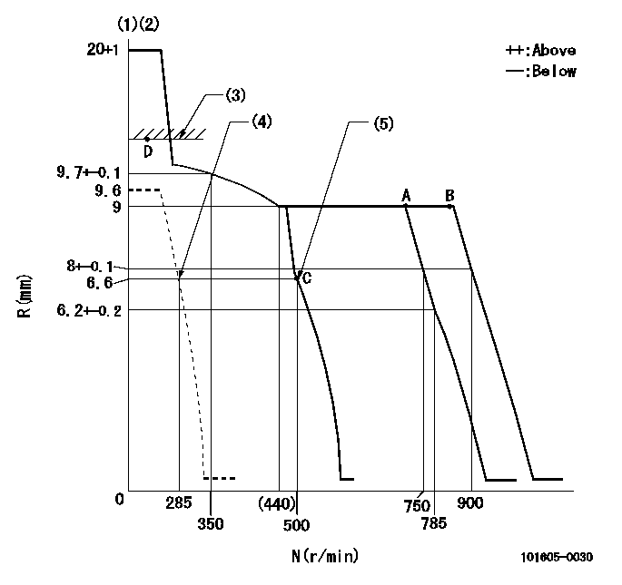
N:Pump speed
R:Rack position (mm)
(1)Target notch: K
(2)Tolerance for racks not indicated: +-0.05mm.
(3)RACK LIMIT
(4)Set idle sub-spring
(5)Main spring setting
----------
K=10
----------
----------
K=10
----------
Speed control lever angle
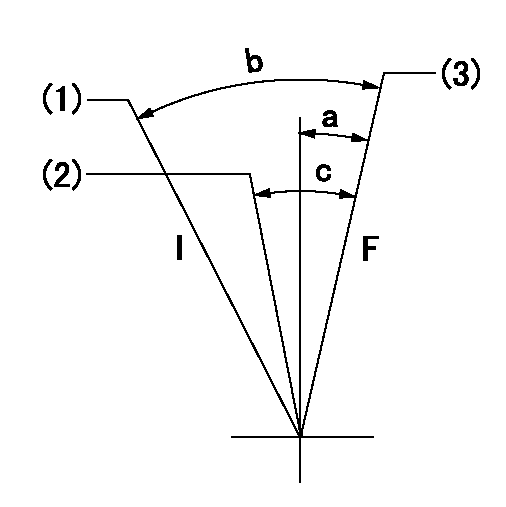
F:Full speed
I:Idle
(1)Stopper bolt setting
(2)Set the pump speed at aa
(3)Set speed at bb (setting at delivery).
----------
aa=750r/min bb=900r/min
----------
a=3deg+-5deg b=15deg+-5deg c=5deg+-5deg
----------
aa=750r/min bb=900r/min
----------
a=3deg+-5deg b=15deg+-5deg c=5deg+-5deg
Stop lever angle
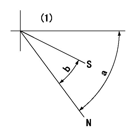
N:Pump normal
S:Stop the pump.
(1)No return spring
----------
----------
a=66.5deg+-5deg b=53deg+-5deg
----------
----------
a=66.5deg+-5deg b=53deg+-5deg
Timing setting

(1)Pump vertical direction
(2)Position of gear mark 'CC' at No 1 cylinder's beginning of injection
(3)B.T.D.C.: aa
(4)-
----------
aa=14deg
----------
a=(100deg)
----------
aa=14deg
----------
a=(100deg)
Information:
Keep all parts clean from contaminants. Contaminants put into the system may cause rapid wear and shortened component life.
1. Remove four bolts (1). Disconnect wires (2) and (3). 2. Remove jake brake (A) by lifting with one hand while holding oil tube (4) to insure it does not come out of jake brake (B).3. Remove jake brake (B). 4. Remove four spacers (5). Install in reverse order.End By:a. install valve cover
Perform Scheduled Oil Sampling on oil wetted compartments after performing service work to check for contaminants left in the system following repair. Contaminants put into the system may cause rapid wear and shortened component life.
Disassemble And Assemble Jake Brake
Start By:a. Remove jake brake
Keep all parts clean from contaminants. Contaminants put into the system may cause rapid wear and shortened component life.
1. Remove oil tubes (1) and (2). Remove the o-ring seals and check for wear or damage. Replace the o-ring seals during assembly if required. 2. Remove snap ring (3), cup (4), spacer (5), springs (6) and (7) and piston (8). 3. Remove three retaining rings (9). Remove clip (10), Springs (11) and (12) and piston (13) from three locations on the jake brake. 4. Remove three bolts (16), washers (15), clips (14) and piston (17). Assemble in reverse order.End By:a. install jake brake
Perform Scheduled Oil Sampling on oil wetted compartments after performing service work to check for contaminants left in the system following repair. Contaminants put into the system may cause rapid wear and shortened component life.
Have questions with 101605-0030?
Group cross 101605-0030 ZEXEL
Isuzu
101605-0030
9 400 612 419
1156033840
INJECTION-PUMP ASSEMBLY
6BG1
6BG1