Information injection-pump assembly
ZEXEL
101603-9990
1016039990

Rating:
Cross reference number
ZEXEL
101603-9990
1016039990
Zexel num
Bosch num
Firm num
Name
101603-9990
DPICO
INJECTION-PUMP ASSEMBLY
6D22 * Q
6D22 * Q
Calibration Data:
Adjustment conditions
Test oil
1404 Test oil ISO4113 or {SAEJ967d}
1404 Test oil ISO4113 or {SAEJ967d}
Test oil temperature
degC
40
40
45
Nozzle and nozzle holder
105780-8140
Bosch type code
EF8511/9A
Nozzle
105780-0000
Bosch type code
DN12SD12T
Nozzle holder
105780-2080
Bosch type code
EF8511/9
Opening pressure
MPa
17.2
Opening pressure
kgf/cm2
175
Injection pipe
Outer diameter - inner diameter - length (mm) mm 6-2-600
Outer diameter - inner diameter - length (mm) mm 6-2-600
Overflow valve
131424-5120
Overflow valve opening pressure
kPa
255
221
289
Overflow valve opening pressure
kgf/cm2
2.6
2.25
2.95
Tester oil delivery pressure
kPa
157
157
157
Tester oil delivery pressure
kgf/cm2
1.6
1.6
1.6
Direction of rotation (viewed from drive side)
Right R
Right R
Injection timing adjustment
Direction of rotation (viewed from drive side)
Right R
Right R
Injection order
1-5-3-6-
2-4
Pre-stroke
mm
4.5
4.45
4.55
Beginning of injection position
Governor side NO.1
Governor side NO.1
Difference between angles 1
Cal 1-5 deg. 60 59.5 60.5
Cal 1-5 deg. 60 59.5 60.5
Difference between angles 2
Cal 1-3 deg. 120 119.5 120.5
Cal 1-3 deg. 120 119.5 120.5
Difference between angles 3
Cal 1-6 deg. 180 179.5 180.5
Cal 1-6 deg. 180 179.5 180.5
Difference between angles 4
Cyl.1-2 deg. 240 239.5 240.5
Cyl.1-2 deg. 240 239.5 240.5
Difference between angles 5
Cal 1-4 deg. 300 299.5 300.5
Cal 1-4 deg. 300 299.5 300.5
Injection quantity adjustment
Adjusting point
-
Rack position
9.6
Pump speed
r/min
700
700
700
Each cylinder's injection qty
mm3/st.
112
109.2
114.8
Basic
*
Fixing the rack
*
Standard for adjustment of the maximum variation between cylinders
*
Injection quantity adjustment_02
Adjusting point
C
Rack position
8+-0.5
Pump speed
r/min
225
225
225
Each cylinder's injection qty
mm3/st.
18.5
15.7
21.3
Fixing the rack
*
Standard for adjustment of the maximum variation between cylinders
*
Injection quantity adjustment_03
Adjusting point
A
Rack position
R1(9.6)
Pump speed
r/min
700
700
700
Average injection quantity
mm3/st.
112
111
113
Basic
*
Fixing the lever
*
Injection quantity adjustment_04
Adjusting point
B
Rack position
R1(9.6)
Pump speed
r/min
1100
1100
1100
Average injection quantity
mm3/st.
113.5
111
116
Difference in delivery
mm3/st.
9
9
9
Fixing the lever
*
Injection quantity adjustment_05
Adjusting point
E
Rack position
-
Pump speed
r/min
100
100
100
Average injection quantity
mm3/st.
140
120
160
Fixing the lever
*
Remarks
After startup boost setting
After startup boost setting
Timer adjustment
Pump speed
r/min
850--
Advance angle
deg.
0
0
0
Remarks
Start
Start
Timer adjustment_02
Pump speed
r/min
800
Advance angle
deg.
0.5
Timer adjustment_03
Pump speed
r/min
900
Advance angle
deg.
0.9
0.4
1.4
Timer adjustment_04
Pump speed
r/min
1150
Advance angle
deg.
3
2.5
3.5
Timer adjustment_05
Pump speed
r/min
-
Advance angle
deg.
4
4
5
Remarks
Measure the actual speed, stop
Measure the actual speed, stop
Test data Ex:
Governor adjustment
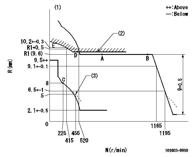
N:Pump speed
R:Rack position (mm)
(1)Tolerance for racks not indicated: +-0.05mm.
(2)Excess fuel setting for starting: SXL
(3)Damper spring setting
----------
SXL=R1(9.6)+0.2mm
----------
----------
SXL=R1(9.6)+0.2mm
----------
Speed control lever angle

F:Full speed
----------
----------
a=10deg+-5deg
----------
----------
a=10deg+-5deg
0000000901
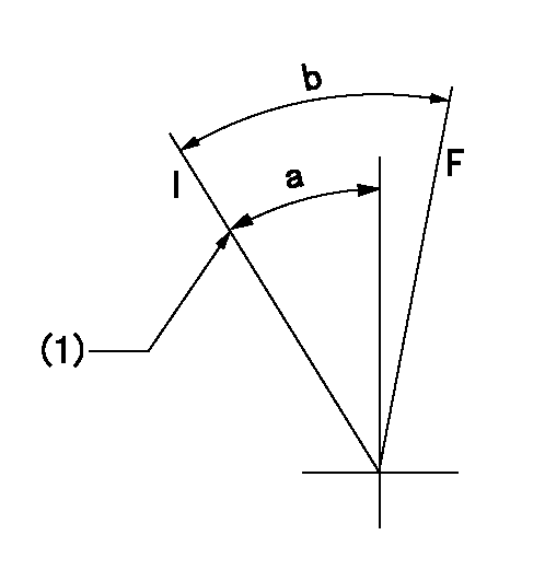
F:Full load
I:Idle
(1)Stopper bolt setting
----------
----------
a=25deg+-5deg b=27.5deg+-3deg
----------
----------
a=25deg+-5deg b=27.5deg+-3deg
Stop lever angle
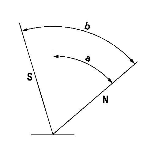
N:Pump normal
S:Stop the pump.
----------
----------
a=54deg+-5deg b=71deg+-5deg
----------
----------
a=54deg+-5deg b=71deg+-5deg
0000001501 MICRO SWITCH
Adjustment of the micro-switch
Adjust the bolt to obtain the following lever position when the micro-switch is ON.
(1)Speed N1
(2)Rack position Ra
----------
N1=325r/min Ra=7.3+-0.1mm
----------
----------
N1=325r/min Ra=7.3+-0.1mm
----------
Timing setting

(1)Pump vertical direction
(2)Coupling's key groove position at No 1 cylinder's beginning of injection
(3)-
(4)-
----------
----------
a=(7deg)
----------
----------
a=(7deg)
Information:
Outside Leaks
Possible Causes/Corrections
Leaks in Hoses or Connections/Check all hoses and connections for visual signs of leakage. If no leaks are seen, look for damage to hoses or loose clamps. Leaks in the Radiator and/or Expansion Tank/Put pressure to the radiator and/or expansion tank with the 9S8140 Cooling System Pressurizing Pump Group and check for leaks. Leaks in the Heater/Put pressure to the cooling system with the 9S8140 Cooling System Pressurizing Pump Group and check the heater for leaks. Leaks in the Water Pump/Check the water pump for leaks before starting the engine, then start the engine and look for leaks. If there are leaks at the water pump, repair or install a new water pump. Cylinder Head Gasket Leakage/Look for leaks along the surface of the cylinder head gasket. If you see leaks, install a new head gasket.Coolant Leaks At The Overflow Tube
Possible Causes/Corrections
Bad Pressure Cap or Relief Valve/Check the sealing surfaces of the pressure cap and the radiator to be sure the cap is sealing correctly. Check the opening pressure and sealing ability of the pressure cap or relief valve with the 9S8140 Cooling System Pressurizing Pump Group. Engine Runs Too Hot/If coolant temperature is too high, pressure will be high enough to move the cap off of the sealing surface in the radiator and cause coolant loss through the overflow tube. See "Overheating" in COOLING SYSTEM TROUBLESHOOTING section. Expansion Tank Too Small or Installed Wrong/The expansion tank can be either a part of the radiator or it can be installed separately from the radiator. The expansion tank must be large enough to hold the expansion of the coolant as it gets warm or has sudden changes in pressure. Make sure the expansion tank is installed correctly, and the size is according to the recommendations of the Truck Manufacturer. Cylinder Head Gasket Leakage or Crack(s) in Cylinder Head or Cylinder Block/Remove the radiator cap and, with the engine running, look for air bubbles in the coolant. Bubbles in the coolant are a sign of probable leakage at the head gasket. Remove the cylinder head from the engine. Check cylinder head, cylinder walls and head gasket surface of the cylinder block for cracks. When the head is installed, use a new head gasket, spacer plate gasket, water seals, and O-ring seals.Inside Leakage
Possible Causes/Corrections
Cylinder Head Gasket Leakage/If the cylinder head gasket leaks between a water passage and an opening into the crankcase, coolant will get into the crankcase. Crack(s) in Cylinder Head/Crack(s) in the upper surface of the cylinder head, or an area between a water passage and an opening into the crankcase, can allow coolant to get into the crankcase. Crack(s) in Cylinder Block/Crack(s) in the cylinder block between a water passage and the crankcase will let coolant get into the crankcase.
Possible Causes/Corrections
Leaks in Hoses or Connections/Check all hoses and connections for visual signs of leakage. If no leaks are seen, look for damage to hoses or loose clamps. Leaks in the Radiator and/or Expansion Tank/Put pressure to the radiator and/or expansion tank with the 9S8140 Cooling System Pressurizing Pump Group and check for leaks. Leaks in the Heater/Put pressure to the cooling system with the 9S8140 Cooling System Pressurizing Pump Group and check the heater for leaks. Leaks in the Water Pump/Check the water pump for leaks before starting the engine, then start the engine and look for leaks. If there are leaks at the water pump, repair or install a new water pump. Cylinder Head Gasket Leakage/Look for leaks along the surface of the cylinder head gasket. If you see leaks, install a new head gasket.Coolant Leaks At The Overflow Tube
Possible Causes/Corrections
Bad Pressure Cap or Relief Valve/Check the sealing surfaces of the pressure cap and the radiator to be sure the cap is sealing correctly. Check the opening pressure and sealing ability of the pressure cap or relief valve with the 9S8140 Cooling System Pressurizing Pump Group. Engine Runs Too Hot/If coolant temperature is too high, pressure will be high enough to move the cap off of the sealing surface in the radiator and cause coolant loss through the overflow tube. See "Overheating" in COOLING SYSTEM TROUBLESHOOTING section. Expansion Tank Too Small or Installed Wrong/The expansion tank can be either a part of the radiator or it can be installed separately from the radiator. The expansion tank must be large enough to hold the expansion of the coolant as it gets warm or has sudden changes in pressure. Make sure the expansion tank is installed correctly, and the size is according to the recommendations of the Truck Manufacturer. Cylinder Head Gasket Leakage or Crack(s) in Cylinder Head or Cylinder Block/Remove the radiator cap and, with the engine running, look for air bubbles in the coolant. Bubbles in the coolant are a sign of probable leakage at the head gasket. Remove the cylinder head from the engine. Check cylinder head, cylinder walls and head gasket surface of the cylinder block for cracks. When the head is installed, use a new head gasket, spacer plate gasket, water seals, and O-ring seals.Inside Leakage
Possible Causes/Corrections
Cylinder Head Gasket Leakage/If the cylinder head gasket leaks between a water passage and an opening into the crankcase, coolant will get into the crankcase. Crack(s) in Cylinder Head/Crack(s) in the upper surface of the cylinder head, or an area between a water passage and an opening into the crankcase, can allow coolant to get into the crankcase. Crack(s) in Cylinder Block/Crack(s) in the cylinder block between a water passage and the crankcase will let coolant get into the crankcase.
Have questions with 101603-9990?
Group cross 101603-9990 ZEXEL
Dpico
Nissan-Diesel
Dpico
China
Nissan-Diesel
Hyundai
Daewoo
Dpico
Daewoo
Dpico
101603-9990
INJECTION-PUMP ASSEMBLY
6D22
6D22