Information injection-pump assembly
ZEXEL
101603-9970
1016039970

Rating:
Service parts 101603-9970 INJECTION-PUMP ASSEMBLY:
1.
_
7.
COUPLING PLATE
8.
_
9.
_
10.
NOZZLE AND HOLDER ASSY
11.
Nozzle and Holder
12.
Open Pre:MPa(Kqf/cm2)
13.
NOZZLE-HOLDER
14.
NOZZLE
15.
NOZZLE SET
Include in #1:
101603-9970
as INJECTION-PUMP ASSEMBLY
Include in #2:
104741-5970
as _
Cross reference number
ZEXEL
101603-9970
1016039970
Zexel num
Bosch num
Firm num
Name
Calibration Data:
Adjustment conditions
Test oil
1404 Test oil ISO4113 or {SAEJ967d}
1404 Test oil ISO4113 or {SAEJ967d}
Test oil temperature
degC
40
40
45
Nozzle and nozzle holder
105780-8140
Bosch type code
EF8511/9A
Nozzle
105780-0000
Bosch type code
DN12SD12T
Nozzle holder
105780-2080
Bosch type code
EF8511/9
Opening pressure
MPa
17.2
Opening pressure
kgf/cm2
175
Injection pipe
Outer diameter - inner diameter - length (mm) mm 6-2-600
Outer diameter - inner diameter - length (mm) mm 6-2-600
Overflow valve
131424-1520
Overflow valve opening pressure
kPa
157
123
191
Overflow valve opening pressure
kgf/cm2
1.6
1.25
1.95
Tester oil delivery pressure
kPa
157
157
157
Tester oil delivery pressure
kgf/cm2
1.6
1.6
1.6
Direction of rotation (viewed from drive side)
Right R
Right R
Injection timing adjustment
Direction of rotation (viewed from drive side)
Right R
Right R
Injection order
6-2-4-1-
5-3
Pre-stroke
mm
4.6
4.55
4.65
Beginning of injection position
Drive side NO.1
Drive side NO.1
Difference between angles 1
Cal 6-2 deg. 60 59.5 60.5
Cal 6-2 deg. 60 59.5 60.5
Difference between angles 2
Cal 6-4 deg. 120 119.5 120.5
Cal 6-4 deg. 120 119.5 120.5
Difference between angles 3
Cal 6-1 deg. 180 179.5 180.5
Cal 6-1 deg. 180 179.5 180.5
Difference between angles 4
Cal 6-5 deg. 240 239.5 240.5
Cal 6-5 deg. 240 239.5 240.5
Difference between angles 5
Cal 6-3 deg. 300 299.5 300.5
Cal 6-3 deg. 300 299.5 300.5
Injection quantity adjustment
Adjusting point
B
Rack position
10.6
Pump speed
r/min
1250
1250
1250
Average injection quantity
mm3/st.
86.6
85.6
87.6
Max. variation between cylinders
%
0
-2
2
Basic
*
Fixing the lever
*
Injection quantity adjustment_02
Adjusting point
C
Rack position
10
Pump speed
r/min
500
500
500
Average injection quantity
mm3/st.
67.1
64.1
70.1
Fixing the lever
*
Injection quantity adjustment_03
Adjusting point
D
Rack position
8.4+-0.5
Pump speed
r/min
250
250
250
Average injection quantity
mm3/st.
8
6.5
9.5
Max. variation between cylinders
%
0
-15
15
Fixing the rack
*
Injection quantity adjustment_04
Adjusting point
E
Rack position
-
Pump speed
r/min
100
100
100
Average injection quantity
mm3/st.
100
100
Fixing the lever
*
Remarks
After startup boost setting
After startup boost setting
Timer adjustment
Pump speed
r/min
750--
Advance angle
deg.
0
0
0
Remarks
Start
Start
Timer adjustment_02
Pump speed
r/min
700
Advance angle
deg.
0.5
Timer adjustment_03
Pump speed
r/min
1250
Advance angle
deg.
4
3.5
4.5
Remarks
Finish
Finish
Test data Ex:
Governor adjustment
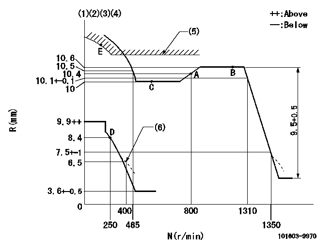
N:Pump speed
R:Rack position (mm)
(1)Lever ratio: RT
(2)Target shim dimension: TH
(3)Tolerance for racks not indicated: +-0.05mm.
(4)Microswitch adjustment unnecessary.
(5)Boost compensator excessive fuel lever at operation: L1 (at N = N1)
(6)Damper spring setting
----------
RT=1 TH=2mm L1=10.7+0.2mm N1=400r/min
----------
----------
RT=1 TH=2mm L1=10.7+0.2mm N1=400r/min
----------
Speed control lever angle

F:Full speed
----------
----------
a=6deg+-5deg
----------
----------
a=6deg+-5deg
0000000901
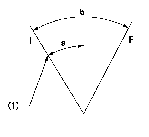
F:Full load
I:Idle
(1)Stopper bolt setting
----------
----------
a=10deg+-5deg b=24deg+-3deg
----------
----------
a=10deg+-5deg b=24deg+-3deg
Stop lever angle

N:Pump normal
S:Stop the pump.
----------
----------
a=20deg+-5deg b=71deg+-5deg
----------
----------
a=20deg+-5deg b=71deg+-5deg
Timing setting

(1)Pump vertical direction
(2)Coupling's key groove position for the No. 6 cylinder's beginning of injection
(3)-
(4)-
----------
----------
a=(60deg)
----------
----------
a=(60deg)
Information:
White Smoke
Possible Causes/Corrections
Cold Outside Temperatures/When the air outside is cold, the cylinder temperature is cooler. Not all the fuel will burn in the cylinders. The fuel which does not burn comes out the exhaust as white smoke. White smoke is normal in cold temperatures until the engine operates long enough to become warm. There will be less white smoke if No. 1 diesel fuel is used. Long Idle Periods/When an engine runs at idle speed for a long period of time, the cylinders cool and all of the fuel does not burn. Do not idle an engine for a long period of time. Stop an engine when it is not in use. If long idle periods are necessary, use No. 1 diesel fuel. Engine Operating Temperature Too Low/This can cause white smoke on start-up. If the smoke is slow to clear from the exhaust, check and make a replacement of the thermostat if needed. Low Quality Fuel/Test the engine using fuel according to recommendations by Caterpillar Tractor Co. For more information see Special Instruction, Form No. SEHS7067, Fuel Recommendations For Caterpillar Diesel Engines. Air in Fuel System/With air in the fuel system, the engine will normally be difficult to start, run rough and release a large amount of white smoke. If the engine will not start, loosen a fuel injection line nut and crank the engine until fuel comes out. Tighten the fuel line nut. Start the engine. If the engine still does not run smooth or releases a large amount of white smoke, loosen the fuel line nuts one at a time until the fuel that comes out is free of air. Tighten the fuel line nuts. If the air can not be removed in this way, put 35 kPa (5 psi) of air pressure to the fuel tank.
Do not use more than 55 kPa (8 psi) of air pressure in the fuel tank or damage to the tank may result.
Check for leakage at the connections between the fuel tank and the fuel transfer pump. If leaks are found, tighten the connections or replace the lines. If there are no visual leaks, remove the fuel supply line from the tank and connect it to an outside fuel supply. If this corrects the problem, the suction line (standpipe) inside the fuel tank has a leak. Fuel Injection Timing Not Correct/Check and make necessary adjustments as in Testing and Adjusting section of this Service Manual. Valve Adjustment Not Correct/Check and make necessary adjustments as in Testing and Adjusting section of this Service Manual. Intake valve clearance is 0.38 mm (.015 in.) and exhaust valve clearance is 0.64 mm (.025 in.). Bad Fuel Nozzle(s)/Bad fuel nozzles will normally cause the engine to "misfire" and run rough, but can cause too much smoke with the engine still running smooth. Remove the fuel nozzles and test as in Testing and Adjusting section of this Service Manual. Misfiring Cylinder(s)/See MISFIRING AND RUNNING ROUGH. Coolant Leakage Into Combustion Chamber/Coolant in the combustion chamber can