Information injection-pump assembly
ZEXEL
101603-9960
1016039960
Rating:
Service parts 101603-9960 INJECTION-PUMP ASSEMBLY:
1.
_
7.
COUPLING PLATE
8.
_
9.
_
11.
Nozzle and Holder
12.
Open Pre:MPa(Kqf/cm2)
21.6{220}

15.
NOZZLE SET
Include in #1:
101603-9960
as INJECTION-PUMP ASSEMBLY
Include in #2:
104740-1950
as _
Cross reference number
ZEXEL
101603-9960
1016039960
Zexel num
Bosch num
Firm num
Name
Calibration Data:
Adjustment conditions
Test oil
1404 Test oil ISO4113 or {SAEJ967d}
1404 Test oil ISO4113 or {SAEJ967d}
Test oil temperature
degC
40
40
45
Nozzle and nozzle holder
105780-8140
Bosch type code
EF8511/9A
Nozzle
105780-0000
Bosch type code
DN12SD12T
Nozzle holder
105780-2080
Bosch type code
EF8511/9
Opening pressure
MPa
17.2
Opening pressure
kgf/cm2
175
Injection pipe
Outer diameter - inner diameter - length (mm) mm 6-2-600
Outer diameter - inner diameter - length (mm) mm 6-2-600
Overflow valve
131424-5120
Overflow valve opening pressure
kPa
255
221
289
Overflow valve opening pressure
kgf/cm2
2.6
2.25
2.95
Tester oil delivery pressure
kPa
157
157
157
Tester oil delivery pressure
kgf/cm2
1.6
1.6
1.6
Direction of rotation (viewed from drive side)
Right R
Right R
Injection timing adjustment
Direction of rotation (viewed from drive side)
Right R
Right R
Injection order
1-5-3-6-
2-4
Pre-stroke
mm
4.5
4.45
4.55
Beginning of injection position
Governor side NO.1
Governor side NO.1
Difference between angles 1
Cal 1-5 deg. 60 59.5 60.5
Cal 1-5 deg. 60 59.5 60.5
Difference between angles 2
Cal 1-3 deg. 120 119.5 120.5
Cal 1-3 deg. 120 119.5 120.5
Difference between angles 3
Cal 1-6 deg. 180 179.5 180.5
Cal 1-6 deg. 180 179.5 180.5
Difference between angles 4
Cyl.1-2 deg. 240 239.5 240.5
Cyl.1-2 deg. 240 239.5 240.5
Difference between angles 5
Cal 1-4 deg. 300 299.5 300.5
Cal 1-4 deg. 300 299.5 300.5
Injection quantity adjustment
Adjusting point
A
Rack position
9.4
Pump speed
r/min
1100
1100
1100
Average injection quantity
mm3/st.
99.5
97.5
101.5
Max. variation between cylinders
%
0
-2.5
2.5
Basic
*
Fixing the lever
*
Injection quantity adjustment_02
Adjusting point
C
Rack position
7.4+-0.5
Pump speed
r/min
400
400
400
Average injection quantity
mm3/st.
17.5
15.5
19.5
Max. variation between cylinders
%
0
-15
15
Fixing the rack
*
Injection quantity adjustment_03
Adjusting point
D
Rack position
-
Pump speed
r/min
100
100
100
Average injection quantity
mm3/st.
145
125
165
Fixing the lever
*
Rack limit
*
Timer adjustment
Pump speed
r/min
1100++
Advance angle
deg.
0.5
Timer adjustment_02
Pump speed
r/min
-
Advance angle
deg.
4.5
4.5
4.5
Remarks
Measure the actual speed, stop
Measure the actual speed, stop
Test data Ex:
Governor adjustment
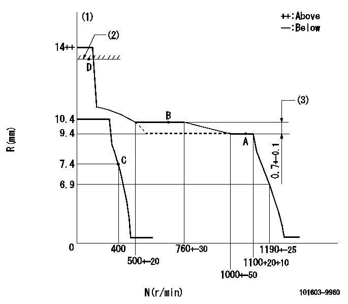
N:Pump speed
R:Rack position (mm)
(1)Target notch: K
(2)RACK LIMIT
(3)Rack difference between N = N1 and N = N2
----------
K=10 N1=1100r/min N2=725r/min
----------
----------
K=10 N1=1100r/min N2=725r/min
----------
Speed control lever angle

F:Full speed
I:Idle
(1)Stopper bolt setting
----------
----------
a=6deg+-5deg b=24deg+-5deg
----------
----------
a=6deg+-5deg b=24deg+-5deg
Stop lever angle
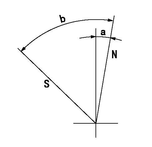
N:Pump normal
S:Stop the pump.
----------
----------
a=2.5deg+-5deg b=53deg+-5deg
----------
----------
a=2.5deg+-5deg b=53deg+-5deg
Timing setting

(1)Pump vertical direction
(2)Coupling's key groove position at No 1 cylinder's beginning of injection
(3)-
(4)-
----------
----------
a=(7deg)
----------
----------
a=(7deg)
Information:
Possible Causes/Corrections
Air or Water in Fuel System/With air in the fuel system, the engine will normally be difficult to start, run rough and release a large amount of white smoke. If the engine will not start, loosen a fuel injection line nut and crank the engine until fuel comes out. Tighten the fuel line nut. Start the engine. If the engine does not run smooth or releases a large amount of white smoke, loosen the fuel line nuts one at a time until the fuel that comes out is free of air. Tighten the fuel lines nuts. If the air can not be removed in this way, put 35 kPa (5 psi) of air pressure to the fuel tank.
Do not use more than 55 kPa (8 psi) of air pressure in the fuel tank or damage to the tank may result.
Check for leaks at the connections between the fuel tank and the fuel transfer pump. If leaks are found, tighten the connections or replace the lines. If there are no visual leaks, remove the fuel supply line from the tank and connect it to an outside fuel supply. If this corrects the problem, the suction line (standpipe) inside the fuel tank has a leak.Water in the fuel can cause rough running and possible fuel system damage. Valve Adjustment Not Correct/Check and make necessary adjustments as in Testing and Adjusting section of this Service Manual. Intake valve clearance is 0.38 mm (.015 in.) and exhaust valve clearance is 0.64 mm (.025 in.). Also check for a bent or broken push rod. Bad Fuel Nozzle(s)/Find a bad nozzle by running engine at the rpm where it runs rough. Loosen the fuel line nut enough to stop fuel supply to that cylinder. Each cylinder must be checked this way. If a cylinder is found where loosening of the nut makes no difference in the rough running, test the nozzle for that cylinder. To test a nozzle, remove the nozzle from the engine and test as in Testing and Adjusting section of this Service Manual. Fuel Leakage From Fuel Injection Line Nut/Tighten nut to 40 7 N m (30 5 lb. ft.). Again check for leakage. Bad Fuel Injection Pump/An injection pump can have a good fuel flow coming from it but cause rough running because of slow timing that is caused by wear on the bottom end of the plunger. See the Testing and Adjusting section in this Service Manual for the correct specifications and procedure to check the plungers and lifters.Fuel pumps which are severely scored from debris can cause rough running, but fuel dilution usually occurs before horsepower is affected.Low installation torque on the fuel pump retaining nut can cause misfire, rough running and low power. Fuel Has a High "Cloud Point"/In cold weather operation this condition should be checked first. The fuel "cloud point" is the temperature at which wax begins to form in the fuel. If the atmospheric temperature is lower than the "cloud point"