Information injection-pump assembly
ZEXEL
101603-9411
1016039411
NISSAN-DIESEL
16713Z5774
16713z5774
Rating:
Cross reference number
ZEXEL
101603-9411
1016039411
NISSAN-DIESEL
16713Z5774
16713z5774
Zexel num
Bosch num
Firm num
Name
101603-9411
16713Z5774 NISSAN-DIESEL
INJECTION-PUMP ASSEMBLY
FE6B * K
FE6B * K
Calibration Data:
Adjustment conditions
Test oil
1404 Test oil ISO4113 or {SAEJ967d}
1404 Test oil ISO4113 or {SAEJ967d}
Test oil temperature
degC
40
40
45
Nozzle and nozzle holder
105780-8140
Bosch type code
EF8511/9A
Nozzle
105780-0000
Bosch type code
DN12SD12T
Nozzle holder
105780-2080
Bosch type code
EF8511/9
Opening pressure
MPa
17.2
Opening pressure
kgf/cm2
175
Injection pipe
Outer diameter - inner diameter - length (mm) mm 6-2-600
Outer diameter - inner diameter - length (mm) mm 6-2-600
Overflow valve
131424-1520
Overflow valve opening pressure
kPa
157
123
191
Overflow valve opening pressure
kgf/cm2
1.6
1.25
1.95
Tester oil delivery pressure
kPa
157
157
157
Tester oil delivery pressure
kgf/cm2
1.6
1.6
1.6
Direction of rotation (viewed from drive side)
Right R
Right R
Injection timing adjustment
Direction of rotation (viewed from drive side)
Right R
Right R
Injection order
1-4-2-6-
3-5
Pre-stroke
mm
3.4
3.35
3.45
Beginning of injection position
Drive side NO.1
Drive side NO.1
Difference between angles 1
Cal 1-4 deg. 60 59.5 60.5
Cal 1-4 deg. 60 59.5 60.5
Difference between angles 2
Cyl.1-2 deg. 120 119.5 120.5
Cyl.1-2 deg. 120 119.5 120.5
Difference between angles 3
Cal 1-6 deg. 180 179.5 180.5
Cal 1-6 deg. 180 179.5 180.5
Difference between angles 4
Cal 1-3 deg. 240 239.5 240.5
Cal 1-3 deg. 240 239.5 240.5
Difference between angles 5
Cal 1-5 deg. 300 299.5 300.5
Cal 1-5 deg. 300 299.5 300.5
Injection quantity adjustment
Adjusting point
-
Rack position
11.8
Pump speed
r/min
600
600
600
Average injection quantity
mm3/st.
66.3
64.7
67.9
Max. variation between cylinders
%
0
-3.5
3.5
Basic
*
Fixing the rack
*
Standard for adjustment of the maximum variation between cylinders
*
Injection quantity adjustment_02
Adjusting point
H
Rack position
9.5+-0.5
Pump speed
r/min
300
300
300
Average injection quantity
mm3/st.
9.5
7.7
11.3
Max. variation between cylinders
%
0
-10
10
Fixing the rack
*
Standard for adjustment of the maximum variation between cylinders
*
Injection quantity adjustment_03
Adjusting point
A
Rack position
R1(11.8)
Pump speed
r/min
600
600
600
Average injection quantity
mm3/st.
66.3
65.3
67.3
Basic
*
Fixing the lever
*
Injection quantity adjustment_04
Adjusting point
B
Rack position
R1-0.2
Pump speed
r/min
900
900
900
Average injection quantity
mm3/st.
73
69.8
76.2
Fixing the lever
*
Injection quantity adjustment_05
Adjusting point
C
Rack position
R1(11.8)
Pump speed
r/min
1500
1500
1500
Average injection quantity
mm3/st.
83.9
79.9
87.9
Fixing the lever
*
Injection quantity adjustment_06
Adjusting point
I
Rack position
-
Pump speed
r/min
100
100
100
Average injection quantity
mm3/st.
84
84
94
Fixing the lever
*
Rack limit
*
Timer adjustment
Pump speed
r/min
850--
Advance angle
deg.
0
0
0
Remarks
Start
Start
Timer adjustment_02
Pump speed
r/min
800
Advance angle
deg.
0.5
Timer adjustment_03
Pump speed
r/min
1500
Advance angle
deg.
4
3.5
4.5
Remarks
Finish
Finish
Test data Ex:
Governor adjustment
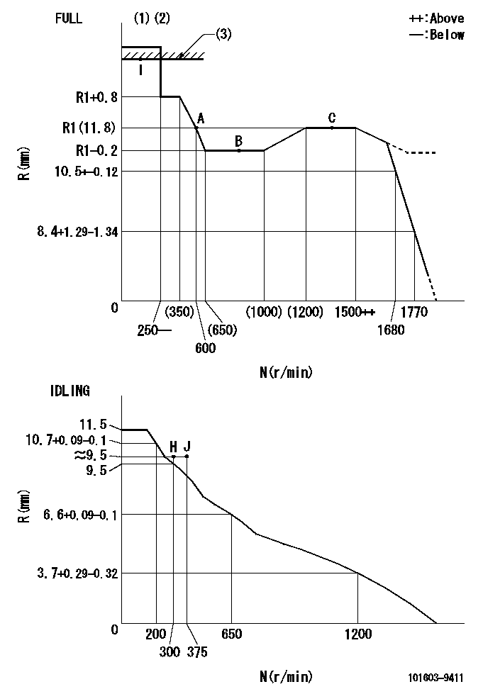
N:Pump speed
R:Rack position (mm)
(1)Torque cam stamping: T1
(2)Tolerance for racks not indicated: +-0.05mm.
(3)RACK LIMIT
----------
T1=C43
----------
----------
T1=C43
----------
Speed control lever angle

F:Full speed
I:Idle
(1)Use the hole at R = aa
(2)Stopper bolt set position 'H'
----------
aa=39mm
----------
a=26.5deg+-5deg b=40deg+-3deg
----------
aa=39mm
----------
a=26.5deg+-5deg b=40deg+-3deg
Stop lever angle

N:Pump normal
S:Stop the pump.
----------
----------
a=20deg+-5deg b=40deg+-5deg
----------
----------
a=20deg+-5deg b=40deg+-5deg
Timing setting

(1)Pump vertical direction
(2)Position of timer's threaded hole at No 1 cylinder's beginning of injection
(3)-
(4)-
----------
----------
a=(60deg)
----------
----------
a=(60deg)
Information:
(1) Setscrew. Adjustment for fuel ratio control.(2) Nut. Tighten to a torque of ... 1.70 0.25 N m (15 2 lb in)(3) Lever for manual shutoff.(4) Setscrew. Adjustment for dimension (6).(5) Nut. Tighten to a torque of ... 1.70 0.25 N m (15 2 lb in)(6) Dimension at shutoff. With manual shutoff lever (3) at the maximum shutoff position, the distance from the end of the lever assembly to the face of the rear governor housing must be ... 28.8 0.5 mm (1.13 .02 in) Make sure setscrew (4) is adjusted to give dimension (6) at assembly.(7) Setscrew. This setscrew is used for the adjustment of dimension (6) on engines that use a shutoff detent. Setscrew (7) is not functional on truck engine arrangments. Make sure nut (8) is tightened to the correct torque to hold setscrew (7) in position.(8) Nut. Tighten to a torque of ... 1.70 0.25 N m (15 2 lb in)(9) Broken link spring. See the Miscellaneous Spring Chart.(10) Torque for screws ... 3.4 0.5 N m (31 4 lb in)(11) Spring to center or preload the flyweights. See the Miscellaneous Spring Chart.(12) Dashpot spring. See the Miscellaneous Spring Chart.(13) Governor spring. See the Governor Spring Chart.(14) Overfueling spring (if equipped). See the Miscellaneous Spring Chart.(15) Tighten the insulated terminal in governor housing to a torque of ... 3.4 0.5 N m (31 4 lb in)(16) Setscrew. Adjustment for torque rise setting.(17) Setscrew. Adjustment for fuel setting.(18) Nut. Tighten the nut on setscrews (16) and (17) to a torque of ... 1.70 0.25 N m (15 2 lb in)(19) Bumper spring. See the Miscellaneous Spring Chart. (20) Lever. Install the shutoff lever as illustrated. Angle (A) and angle (B) from the vertical centerline must be ... 30°(21) Guide. The distance from the end of the guide to the housing gasket surface is dimension (C) ... 11.80 0.25 mm (.464 .010 in)
Have questions with 101603-9411?
Group cross 101603-9411 ZEXEL
Nissan-Diesel
Nissan-Diesel
101603-9411
16713Z5774
INJECTION-PUMP ASSEMBLY
FE6B
FE6B