Information injection-pump assembly
ZEXEL
101603-9410
1016039410
Rating:
Cross reference number
ZEXEL
101603-9410
1016039410
Zexel num
Bosch num
Firm num
Name
101603-9410
INJECTION-PUMP ASSEMBLY
Calibration Data:
Adjustment conditions
Test oil
1404 Test oil ISO4113 or {SAEJ967d}
1404 Test oil ISO4113 or {SAEJ967d}
Test oil temperature
degC
40
40
45
Nozzle and nozzle holder
105780-8140
Bosch type code
EF8511/9A
Nozzle
105780-0000
Bosch type code
DN12SD12T
Nozzle holder
105780-2080
Bosch type code
EF8511/9
Opening pressure
MPa
17.2
Opening pressure
kgf/cm2
175
Injection pipe
Outer diameter - inner diameter - length (mm) mm 6-2-600
Outer diameter - inner diameter - length (mm) mm 6-2-600
Overflow valve
132424-0620
Overflow valve opening pressure
kPa
157
123
191
Overflow valve opening pressure
kgf/cm2
1.6
1.25
1.95
Tester oil delivery pressure
kPa
157
157
157
Tester oil delivery pressure
kgf/cm2
1.6
1.6
1.6
Direction of rotation (viewed from drive side)
Right R
Right R
Injection timing adjustment
Direction of rotation (viewed from drive side)
Right R
Right R
Injection order
1-4-2-6-
3-5
Pre-stroke
mm
3.4
3.35
3.45
Beginning of injection position
Drive side NO.1
Drive side NO.1
Difference between angles 1
Cal 1-4 deg. 60 59.5 60.5
Cal 1-4 deg. 60 59.5 60.5
Difference between angles 2
Cyl.1-2 deg. 120 119.5 120.5
Cyl.1-2 deg. 120 119.5 120.5
Difference between angles 3
Cal 1-6 deg. 180 179.5 180.5
Cal 1-6 deg. 180 179.5 180.5
Difference between angles 4
Cal 1-3 deg. 240 239.5 240.5
Cal 1-3 deg. 240 239.5 240.5
Difference between angles 5
Cal 1-5 deg. 300 299.5 300.5
Cal 1-5 deg. 300 299.5 300.5
Injection quantity adjustment
Adjusting point
-
Rack position
11.8
Pump speed
r/min
600
600
600
Average injection quantity
mm3/st.
66.3
64.7
67.9
Max. variation between cylinders
%
0
-3.5
3.5
Basic
*
Fixing the rack
*
Standard for adjustment of the maximum variation between cylinders
*
Injection quantity adjustment_02
Adjusting point
H
Rack position
9.5+-0.5
Pump speed
r/min
300
300
300
Average injection quantity
mm3/st.
9.5
7.7
11.3
Max. variation between cylinders
%
0
-10
10
Fixing the rack
*
Standard for adjustment of the maximum variation between cylinders
*
Injection quantity adjustment_03
Adjusting point
A
Rack position
R1(11.8)
Pump speed
r/min
600
600
600
Average injection quantity
mm3/st.
66.3
65.3
67.3
Basic
*
Fixing the lever
*
Injection quantity adjustment_04
Adjusting point
B
Rack position
R1-0.2
Pump speed
r/min
900
900
900
Average injection quantity
mm3/st.
73
69.8
76.2
Fixing the lever
*
Injection quantity adjustment_05
Adjusting point
C
Rack position
R1(11.8)
Pump speed
r/min
1500
1500
1500
Average injection quantity
mm3/st.
83.9
79.9
87.9
Fixing the lever
*
Injection quantity adjustment_06
Adjusting point
I
Rack position
-
Pump speed
r/min
100
100
100
Average injection quantity
mm3/st.
84
84
94
Fixing the lever
*
Rack limit
*
Timer adjustment
Pump speed
r/min
850--
Advance angle
deg.
0
0
0
Remarks
Start
Start
Timer adjustment_02
Pump speed
r/min
800
Advance angle
deg.
0.5
Timer adjustment_03
Pump speed
r/min
1500
Advance angle
deg.
4
3.5
4.5
Remarks
Finish
Finish
Test data Ex:
Governor adjustment
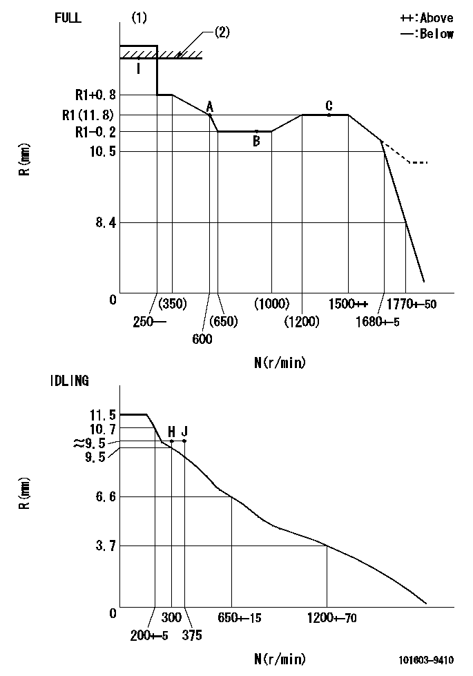
N:Pump speed
R:Rack position (mm)
(1)Torque cam stamping: T1
(2)RACK LIMIT
----------
T1=C43
----------
----------
T1=C43
----------
Speed control lever angle

F:Full speed
I:Idle
(1)Stopper bolt set position 'H'
----------
----------
a=26.5deg+-5deg b=40deg+-3deg
----------
----------
a=26.5deg+-5deg b=40deg+-3deg
Stop lever angle

N:Pump normal
S:Stop the pump.
----------
----------
a=20deg+-5deg b=40deg+-5deg
----------
----------
a=20deg+-5deg b=40deg+-5deg
Timing setting

(1)Pump vertical direction
(2)Position of timer's threaded hole at No 1 cylinder's beginning of injection
(3)-
(4)-
----------
----------
a=(60deg)
----------
----------
a=(60deg)
Information:
Do not heat the gear with a torch. Do not heat the gear to a temperature of more than 315°C (600°F). Heating the gear with a torch or to a temperature of more than 315°C (600°F) may cause the two drive dowels for the automatic timing advance to loosen and come out of the gear.
2. Align slot in gear hub with the pin in the camshaft. Install the gear on the camshaft with timing mark on gear aligned with timing mark on crankshaft gear. Be sure the gear is completely seated against the shoulder of the camshaft.
Do not drive the gear on the camshaft.
3. Align holes in weights with dowels in gear and install the automatic timing advance.4. Align pin (3) in washer with hole (4) in camshaft and install washer (2).5. Install screw (1) and tighten to 7.9 0.6 N m (70 5 lb in). Stake screw in two places.
Installing Washer
(2) Washer. (3) Pin. (4) Hole.
Stake screw (1) carefully. Heavy blows on washer or screw can force the shaft extension too far into the camshaft and eliminate all end clearance.
6. After screw (1) is staked, the gear and weight assembly requires 0.08 to 0.94 mm (.003 to .037 in) end clearance to prevent binding against the washer, camshaft end or camshaft gear.
Staking Screw
(1) Screw.Camshaft Bearings Removal and Installation
Remove camshaft bearings using the 1P5544 Washer (1) and 0S0509 Bolts (2), from the 1P5545 Adapter Group, in conjunction with the 8S2241 Camshaft Bearing Removal and Installation Group, and the 8H0684 Ratchet Box Wrench.
Installing Washer
(1) 1P5544 Washer. (2) 0S0509 Bolt.With removal tools installed on cylinder block, remove bearings.
Removing Camshaft BearingsUse the 1P5545 Adapter Group in conjunction with the 8S2241 Camshaft Bearing Removal and Installation Group, and the 8S0684 Ratchet Box Wrench to install camshaft bearing.
Installing Camshaft BearingsThe 1P5545 Adapter Group pilots in the camshaft bearing bore and also pilots the bearing into the bore. This insures bearing alignment. Install bearings from chamfered side of the bore and align oil hole in bearings with oil holes in cylinder block.To install the camshaft front bearing, it is necessary to machine a notch in the 8S8289 Tube (3) for clearance of the boss that projects above the camshaft bearing bore. Machine the notch 38.1 mm (1.50 in) wide, 9.5 mm (.37 in) deep, with a 3.2 mm (.13 in) radius or chamfer in the corners and on the edges.
Notch In Tube
(3) 8S8289 Tube. (4) 8S8288 Cone. (5) Notch.Invert the 8S8288 Cone (4) and install it in the 8S8289 Tube (3) for installation of the camshaft front bearing.
Installing Camshaft Front Bearing
(3) 8S8289 Tube. (4) 8S8288 Cone.Engine Test Procedure
Lubrication For A Rebuilt Engine
It is very important for a rebuilt engine to have "adequate" (needed) lubrication during the first seconds of operation. A "dry start" (without needed lubrication) on a rebuilt engine can cause bearing damage.When an engine is rebuilt with new parts, oil is put on each part as it is installed. This is generally enough lubrication for engine start-up. However, this lubrication
Have questions with 101603-9410?
Group cross 101603-9410 ZEXEL
Nissan-Diesel
101603-9410
INJECTION-PUMP ASSEMBLY