Information injection-pump assembly
ZEXEL
101603-9401
1016039401
NISSAN-DIESEL
16713Z5773
16713z5773

Rating:
Cross reference number
ZEXEL
101603-9401
1016039401
NISSAN-DIESEL
16713Z5773
16713z5773
Zexel num
Bosch num
Firm num
Name
101603-9401
16713Z5773 NISSAN-DIESEL
INJECTION-PUMP ASSEMBLY
FE6B * K
FE6B * K
Calibration Data:
Adjustment conditions
Test oil
1404 Test oil ISO4113 or {SAEJ967d}
1404 Test oil ISO4113 or {SAEJ967d}
Test oil temperature
degC
40
40
45
Nozzle and nozzle holder
105780-8140
Bosch type code
EF8511/9A
Nozzle
105780-0000
Bosch type code
DN12SD12T
Nozzle holder
105780-2080
Bosch type code
EF8511/9
Opening pressure
MPa
17.2
Opening pressure
kgf/cm2
175
Injection pipe
Outer diameter - inner diameter - length (mm) mm 6-2-600
Outer diameter - inner diameter - length (mm) mm 6-2-600
Overflow valve
131424-1520
Overflow valve opening pressure
kPa
157
123
191
Overflow valve opening pressure
kgf/cm2
1.6
1.25
1.95
Tester oil delivery pressure
kPa
157
157
157
Tester oil delivery pressure
kgf/cm2
1.6
1.6
1.6
Direction of rotation (viewed from drive side)
Right R
Right R
Injection timing adjustment
Direction of rotation (viewed from drive side)
Right R
Right R
Injection order
1-4-2-6-
3-5
Pre-stroke
mm
3.4
3.35
3.45
Beginning of injection position
Drive side NO.1
Drive side NO.1
Difference between angles 1
Cal 1-4 deg. 60 59.5 60.5
Cal 1-4 deg. 60 59.5 60.5
Difference between angles 2
Cyl.1-2 deg. 120 119.5 120.5
Cyl.1-2 deg. 120 119.5 120.5
Difference between angles 3
Cal 1-6 deg. 180 179.5 180.5
Cal 1-6 deg. 180 179.5 180.5
Difference between angles 4
Cal 1-3 deg. 240 239.5 240.5
Cal 1-3 deg. 240 239.5 240.5
Difference between angles 5
Cal 1-5 deg. 300 299.5 300.5
Cal 1-5 deg. 300 299.5 300.5
Injection quantity adjustment
Adjusting point
-
Rack position
11.8
Pump speed
r/min
600
600
600
Average injection quantity
mm3/st.
66.3
64.7
67.9
Max. variation between cylinders
%
0
-3.5
3.5
Basic
*
Fixing the rack
*
Standard for adjustment of the maximum variation between cylinders
*
Injection quantity adjustment_02
Adjusting point
H
Rack position
9.5+-0.5
Pump speed
r/min
300
300
300
Average injection quantity
mm3/st.
9.5
7.7
11.3
Max. variation between cylinders
%
0
-10
10
Fixing the rack
*
Standard for adjustment of the maximum variation between cylinders
*
Injection quantity adjustment_03
Adjusting point
A
Rack position
R1(11.8)
Pump speed
r/min
600
600
600
Average injection quantity
mm3/st.
66.3
65.3
67.3
Basic
*
Fixing the lever
*
Injection quantity adjustment_04
Adjusting point
B
Rack position
R1-0.2
Pump speed
r/min
900
900
900
Average injection quantity
mm3/st.
73
69.8
76.2
Fixing the lever
*
Injection quantity adjustment_05
Adjusting point
C
Rack position
R1(11.8)
Pump speed
r/min
1500
1500
1500
Average injection quantity
mm3/st.
83.9
79.9
87.9
Fixing the lever
*
Injection quantity adjustment_06
Adjusting point
I
Rack position
-
Pump speed
r/min
100
100
100
Average injection quantity
mm3/st.
84
84
94
Fixing the lever
*
Rack limit
*
Timer adjustment
Pump speed
r/min
850--
Advance angle
deg.
0
0
0
Remarks
Start
Start
Timer adjustment_02
Pump speed
r/min
800
Advance angle
deg.
0.5
Timer adjustment_03
Pump speed
r/min
1500
Advance angle
deg.
4
3.5
4.5
Remarks
Finish
Finish
Test data Ex:
Governor adjustment
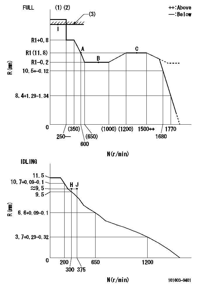
N:Pump speed
R:Rack position (mm)
(1)Torque cam stamping: T1
(2)Tolerance for racks not indicated: +-0.05mm.
(3)RACK LIMIT
----------
T1=C43
----------
----------
T1=C43
----------
Speed control lever angle

F:Full speed
I:Idle
(1)Stopper bolt set position 'H'
----------
----------
a=26.5deg+-5deg b=40deg+-3deg
----------
----------
a=26.5deg+-5deg b=40deg+-3deg
Stop lever angle

N:Pump normal
S:Stop the pump.
----------
----------
a=20deg+-5deg b=40deg+-5deg
----------
----------
a=20deg+-5deg b=40deg+-5deg
Timing setting

(1)Pump vertical direction
(2)Position of timer's threaded hole at No 1 cylinder's beginning of injection
(3)-
(4)-
----------
----------
a=(60deg)
----------
----------
a=(60deg)
Information:
start by:a) remove flywheel housingb) remove valve liftersc) remove pistonsd) remove timing gear cover and oil pump1. Fasten a hoist and put the engine in position on tool (A).2. Turn the crankshaft until the timing mark on the crankshaft gear is in alignment with the timing mark on the camshaft gear. For more detail about removal of main bearings see REMOVE AND INSTALL CRANKSHAFT MAIN BEARINGS. 3. Remove bolts (1) and main bearing caps (2). Remove the lower halves of the main bearings from the caps.4. Install two of the bolts that hold the flywheel in place in the end of crankshaft. 5. Fasten a hoist and remove crankshaft (3) from the engine. The weight of the crankshaft is 54 kg (120 lb.).
Be careful not to cause damage to the crankshaft journals when the crankshaft is removed.
6. Remove the upper halves of the main bearings from the cylinder block.7. Install tooling (B) and remove the gear from the crankshaft. Install Crankshaft And Gear
1. Install the key for the crankshaft gear so it is even with the end of the crankshaft.2. Heat the crankshaft gear to a maximum temperature of 260°C (500°F). Install the gear on the crankshaft with the timing mark on the gear toward the pulley end of the crankshaft.3. Install the thrust bearing for the No. 4 main. Install the bearings dry when the clearance checks are made. Put clean engine oil on the bearings for final assembly.4. Install the upper main bearings (the bearings with oil hole) into the engine block.5. Install two of the bolts that hold the flywheel in place in the end of the crankshaft. Fasten a hoist and put the crankshaft in position in the block. Make sure the timing mark on the crankshaft gear is in alignment with the timing mark on the camshaft gear. For more detail about installation of main bearings see REMOVE AND INSTALL CRANKSHAFT MAIN BEARINGS.
When the bearing caps are installed, make sure the number on the side of the cap is next to and respective with the number on the engine block.
When the bearing clearance is checked and the engine is in a vertical position, the crankshaft will have to be lifted up with a force equal to the weight of the crankshaft and held against the upper halves of the main bearings to get a correct measurement with Plastigage. The Plastigage will not hold the weight of the crankshaft and give a correct indication. If the engine is in a horizontal position, such as on an engine stand, it is not necessary to hold the crankshaft up. Do not turn crankshaft when Plastigage is in position to check clearance. 6. Check the bearing clearance with Plastigage. Put the lower main bearings into the caps. Put the caps in position and install the bolts. Tighten the bolts in number sequence as follows: a) Tighten bolts 1 through 10 to a torque of 40 4 N m (30 3 lb.ft.).
Do not use an impact
Have questions with 101603-9401?
Group cross 101603-9401 ZEXEL
Nissan-Diesel
101603-9401
16713Z5773
INJECTION-PUMP ASSEMBLY
FE6B
FE6B