Information injection-pump assembly
ZEXEL
101603-9330
1016039330
NISSAN-DIESEL
16713Z5762
16713z5762
Rating:
Cross reference number
ZEXEL
101603-9330
1016039330
NISSAN-DIESEL
16713Z5762
16713z5762
Zexel num
Bosch num
Firm num
Name
101603-9330
16713Z5762 NISSAN-DIESEL
INJECTION-PUMP ASSEMBLY
FE6A * K
FE6A * K
Calibration Data:
Adjustment conditions
Test oil
1404 Test oil ISO4113 or {SAEJ967d}
1404 Test oil ISO4113 or {SAEJ967d}
Test oil temperature
degC
40
40
45
Nozzle and nozzle holder
105780-8140
Bosch type code
EF8511/9A
Nozzle
105780-0000
Bosch type code
DN12SD12T
Nozzle holder
105780-2080
Bosch type code
EF8511/9
Opening pressure
MPa
17.2
Opening pressure
kgf/cm2
175
Injection pipe
Outer diameter - inner diameter - length (mm) mm 6-2-600
Outer diameter - inner diameter - length (mm) mm 6-2-600
Overflow valve opening pressure
kPa
157
123
191
Overflow valve opening pressure
kgf/cm2
1.6
1.25
1.95
Tester oil delivery pressure
kPa
157
157
157
Tester oil delivery pressure
kgf/cm2
1.6
1.6
1.6
Direction of rotation (viewed from drive side)
Right R
Right R
Injection timing adjustment
Direction of rotation (viewed from drive side)
Right R
Right R
Injection order
1-4-2-6-
3-5
Pre-stroke
mm
3
2.95
3.05
Beginning of injection position
Drive side NO.1
Drive side NO.1
Difference between angles 1
Cal 1-4 deg. 60 59.5 60.5
Cal 1-4 deg. 60 59.5 60.5
Difference between angles 2
Cyl.1-2 deg. 120 119.5 120.5
Cyl.1-2 deg. 120 119.5 120.5
Difference between angles 3
Cal 1-6 deg. 180 179.5 180.5
Cal 1-6 deg. 180 179.5 180.5
Difference between angles 4
Cal 1-3 deg. 240 239.5 240.5
Cal 1-3 deg. 240 239.5 240.5
Difference between angles 5
Cal 1-5 deg. 300 299.5 300.5
Cal 1-5 deg. 300 299.5 300.5
Injection quantity adjustment
Adjusting point
A
Rack position
8.1
Pump speed
r/min
600
600
600
Average injection quantity
mm3/st.
42.2
41.2
43.2
Max. variation between cylinders
%
0
-3.5
3.5
Basic
*
Fixing the lever
*
Injection quantity adjustment_02
Adjusting point
B
Rack position
7.8
Pump speed
r/min
1000
1000
1000
Average injection quantity
mm3/st.
53.3
52.3
54.3
Max. variation between cylinders
%
0
-10
10
Fixing the lever
*
Injection quantity adjustment_03
Adjusting point
-
Rack position
7+-0.5
Pump speed
r/min
300
300
300
Average injection quantity
mm3/st.
9
7.2
10.8
Max. variation between cylinders
%
0
-10
10
Fixing the rack
*
Injection quantity adjustment_04
Adjusting point
D
Rack position
-
Pump speed
r/min
100
100
100
Average injection quantity
mm3/st.
80
80
Fixing the lever
*
Remarks
After startup boost setting
After startup boost setting
Timer adjustment
Pump speed
r/min
(1140)
Advance angle
deg.
0
0
0
Remarks
Start
Start
Timer adjustment_02
Pump speed
r/min
1500
Advance angle
deg.
4
3.5
4.5
Remarks
Finish
Finish
Test data Ex:
Governor adjustment
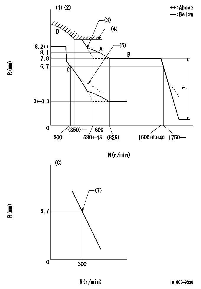
N:Pump speed
R:Rack position (mm)
(1)Lever ratio: RT
(2)Target shim dimension: TH
(3)The torque control spring must does not have a set force.
(4)Excess fuel setting for starting: SXL
(5)Damper spring setting: DL
(6)Variable speed specification: idling adjustment
(7)Main spring setting
----------
RT=1 TH=2mm SXL=10.5-0.2mm DL=6-0.2mm
----------
----------
RT=1 TH=2mm SXL=10.5-0.2mm DL=6-0.2mm
----------
Speed control lever angle
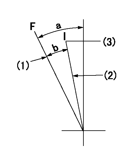
F:Full speed
I:Idle
(1)Set the pump speed at aa
(2)Stopper bolt setting
(3)Set the pump speed at bb.
----------
aa=1600r/min bb=300r/min
----------
a=(26deg)+-5deg b=(22deg)+-5deg
----------
aa=1600r/min bb=300r/min
----------
a=(26deg)+-5deg b=(22deg)+-5deg
0000000901

F:Full load
I:Idle
(1)Stopper bolt setting
----------
----------
a=17deg+-5deg b=19deg+-3deg
----------
----------
a=17deg+-5deg b=19deg+-3deg
Stop lever angle
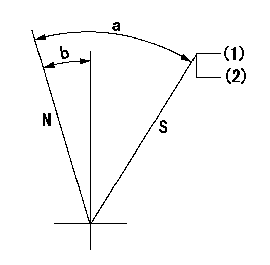
N:Pump normal
S:Stop the pump.
(1)Use the pin at R = aa
(2)Rack position bb
----------
aa=20mm bb=(1.2)mm
----------
a=71deg+-5deg b=40deg+-5deg
----------
aa=20mm bb=(1.2)mm
----------
a=71deg+-5deg b=40deg+-5deg
Timing setting

(1)Pump vertical direction
(2)Position of timer's threaded hole at No 1 cylinder's beginning of injection
(3)-
(4)-
----------
----------
a=(60deg)
----------
----------
a=(60deg)
Information:
Install Crankcase Ventilator Valve
1. Put gasket (2) and ventilator valve (1) in position. 2. Install the bolts and tighten them to a torque of 3.4 0.5 N m (30 4 lb.in.).Disassemble Crankcase Ventilator Valve
The crankcase ventilator valve can be disassembled while installed on the engine. The valve was removed for better photo illustration.1. Remove screws (2) that hold cover (3) on housing (1). 2. Remove cover (3) and spring (4) from the housing. 3. Remove the piston, sleeve (8), retainer (9), and diaphragm (7) from the housing as a unit. 4. Remove inner sleeve (6) and gasket (5) from the housing. 5. Remove nut (12), washer (13), spacer (11), piston (10), diaphragm (7), and the retainer from sleeve (8).Assemble Crankcase Ventilator Valve
1. Put 5H2471 Gasket Cement on both sides of gasket (2). Install the gasket on housing (1). 2. Install inner sleeve (3) in the housing.3. Put piston (6) in position next to the side of diaphragm (4) that has identification "PISTON SIDE".4. Put retainer (5) in the diaphragm. 5. Put the screw through sleeve (7), retainer, diaphragm, and the piston.6. Install spacer (8), washer, and nut (9) on the screw. 7. Put 5H2471 Gasket Cement on the contact surfaces of the diaphragm. Install the sleeve, retainer, diaphragm, and piston in the inner sleeve and housing.8. Put the spring and cover in position on the housing and install the screws that hold the cover in place.
Have questions with 101603-9330?
Group cross 101603-9330 ZEXEL
Nissan-Diesel
Nissan-Diesel
Nissan-Diesel
101603-9330
16713Z5762
INJECTION-PUMP ASSEMBLY
FE6A
FE6A