Information injection-pump assembly
ZEXEL
101603-9322
1016039322
NISSAN-DIESEL
16700Z5673
16700z5673
Rating:
Cross reference number
ZEXEL
101603-9322
1016039322
NISSAN-DIESEL
16700Z5673
16700z5673
Zexel num
Bosch num
Firm num
Name
101603-9322
16700Z5673 NISSAN-DIESEL
INJECTION-PUMP ASSEMBLY
FE6A * K
FE6A * K
Calibration Data:
Adjustment conditions
Test oil
1404 Test oil ISO4113 or {SAEJ967d}
1404 Test oil ISO4113 or {SAEJ967d}
Test oil temperature
degC
40
40
45
Nozzle and nozzle holder
105780-8140
Bosch type code
EF8511/9A
Nozzle
105780-0000
Bosch type code
DN12SD12T
Nozzle holder
105780-2080
Bosch type code
EF8511/9
Opening pressure
MPa
17.2
Opening pressure
kgf/cm2
175
Injection pipe
Outer diameter - inner diameter - length (mm) mm 6-2-600
Outer diameter - inner diameter - length (mm) mm 6-2-600
Overflow valve
131424-1520
Overflow valve opening pressure
kPa
157
123
191
Overflow valve opening pressure
kgf/cm2
1.6
1.25
1.95
Tester oil delivery pressure
kPa
157
157
157
Tester oil delivery pressure
kgf/cm2
1.6
1.6
1.6
Direction of rotation (viewed from drive side)
Right R
Right R
Injection timing adjustment
Direction of rotation (viewed from drive side)
Right R
Right R
Injection order
1-4-2-6-
3-5
Pre-stroke
mm
3
2.95
3.05
Beginning of injection position
Drive side NO.1
Drive side NO.1
Difference between angles 1
Cal 1-4 deg. 60 59.5 60.5
Cal 1-4 deg. 60 59.5 60.5
Difference between angles 2
Cyl.1-2 deg. 120 119.5 120.5
Cyl.1-2 deg. 120 119.5 120.5
Difference between angles 3
Cal 1-6 deg. 180 179.5 180.5
Cal 1-6 deg. 180 179.5 180.5
Difference between angles 4
Cal 1-3 deg. 240 239.5 240.5
Cal 1-3 deg. 240 239.5 240.5
Difference between angles 5
Cal 1-5 deg. 300 299.5 300.5
Cal 1-5 deg. 300 299.5 300.5
Injection quantity adjustment
Adjusting point
A
Rack position
8.2
Pump speed
r/min
600
600
600
Average injection quantity
mm3/st.
42
41
43
Max. variation between cylinders
%
0
-3.5
3.5
Basic
*
Fixing the lever
*
Injection quantity adjustment_02
Adjusting point
B
Rack position
8
Pump speed
r/min
1000
1000
1000
Average injection quantity
mm3/st.
53
52
54
Max. variation between cylinders
%
0
-10
10
Fixing the lever
*
Injection quantity adjustment_03
Adjusting point
-
Rack position
7+-0.5
Pump speed
r/min
300
300
300
Average injection quantity
mm3/st.
9
7.2
10.8
Max. variation between cylinders
%
0
-10
10
Fixing the rack
*
Remarks
Adjust only variation between cylinders; adjust governor according to governor specifications.
Adjust only variation between cylinders; adjust governor according to governor specifications.
Injection quantity adjustment_04
Adjusting point
D
Rack position
-
Pump speed
r/min
100
100
100
Average injection quantity
mm3/st.
80
80
Fixing the lever
*
Remarks
After startup boost setting
After startup boost setting
Timer adjustment
Pump speed
r/min
(1140)
Advance angle
deg.
0
0
0
Remarks
Start
Start
Timer adjustment_02
Pump speed
r/min
1500
Advance angle
deg.
4
3.5
4.5
Remarks
Finish
Finish
Test data Ex:
Governor adjustment
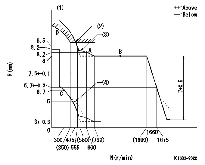
N:Pump speed
R:Rack position (mm)
(1)Tolerance for racks not indicated: +-0.05mm.
(2)Excess fuel setting for starting: SXL (N = N1)
(3)The torque control spring must does not have a set force.
(4)Damper spring setting
----------
SXL=10.5-0.2mm N1=380r/min
----------
----------
SXL=10.5-0.2mm N1=380r/min
----------
0000000901

F:Full load
I:Idle
(1)Stopper bolt setting
----------
----------
a=17deg+-5deg b=18.5deg+-3deg
----------
----------
a=17deg+-5deg b=18.5deg+-3deg
Stop lever angle
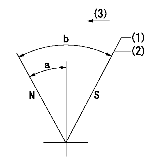
N:Pump normal
S:Stop the pump.
(1)Use the pin at R = aa
(2)Rack position bb
(3)Drive side
----------
aa=20mm bb=(1.2)mm
----------
a=40deg+-5deg b=71deg+-5deg
----------
aa=20mm bb=(1.2)mm
----------
a=40deg+-5deg b=71deg+-5deg
Timing setting

(1)Pump vertical direction
(2)Position of timer's threaded hole at No 1 cylinder's beginning of injection
(3)-
(4)-
----------
----------
a=(60deg)
----------
----------
a=(60deg)
Information:
It is not necessary to remove the oil pan.1. Remove the coolant from the cooling system.2. Use tooling (A) and remove oil filter (2). 3. Loosen clamps (1) and disconnect the bases.4. Remove bolt (4) and three bolts from behind the oil cooler. 5. Remove oil filter base and engine oil cooler (3) as a unit.Install Engine Oil Cooler And Oil Filter Base
1. Inspect the O-ring seals in the oil filter base. Install new seals if needed. Put oil on the seal. 2. Put oil filter base and oil cooler (1) in position on the engine.3. Install the four bolts that hold the oil cooler in place. 4. Connect the two hoses and install clamps (2).5. Install oil filter (3). See the instructions on the oil filter.Disassemble Engine Oil Cooler And Oil Filter Base
start by:a) remove engine oil cooler and oil filter base1. Remove bolts (1) and make a separation of cover (2) from the oil filter base. 2. Remove nuts (3) and make a separation of the oil cooler from oil filter base (4). 3. Remove divider (6) from oil cooler (5). 4. Remove plug (9), spring (8) and bypass valve (7). 5. Remove plug (12), spring (11) and bypass valve (10) from the oil filter base. Assemble Engine Oil Cooler And Oil Filter Base
1. Put valve (1) and spring (2) in position in oil filter base (4). 2. Install plug (3).3. Put the valve and spring (5) in position and install plug (6). 4. Put divider (7) in position between the fifth and sixth plates from the flange and on the same end as the short stud. 5. Install oil filter base (4) in position on oil cooler (8) and install the nuts. Tighten the nuts to a torque of 22 3 N m (16 2 lb.ft.).6. Install the gasket, cover (9) and the bolts. end by:a) install engine oil cooler and oil filter base
Have questions with 101603-9322?
Group cross 101603-9322 ZEXEL
Nissan-Diesel
Nissan-Diesel
Nissan-Diesel
101603-9322
16700Z5673
INJECTION-PUMP ASSEMBLY
FE6A
FE6A