Information injection-pump assembly
ZEXEL
101603-9310
1016039310
Rating:
Cross reference number
ZEXEL
101603-9310
1016039310
Zexel num
Bosch num
Firm num
Name
101603-9310
INJECTION-PUMP ASSEMBLY
Calibration Data:
Adjustment conditions
Test oil
1404 Test oil ISO4113 or {SAEJ967d}
1404 Test oil ISO4113 or {SAEJ967d}
Test oil temperature
degC
40
40
45
Nozzle and nozzle holder
105780-8140
Bosch type code
EF8511/9A
Nozzle
105780-0000
Bosch type code
DN12SD12T
Nozzle holder
105780-2080
Bosch type code
EF8511/9
Opening pressure
MPa
17.2
Opening pressure
kgf/cm2
175
Injection pipe
Outer diameter - inner diameter - length (mm) mm 6-2-600
Outer diameter - inner diameter - length (mm) mm 6-2-600
Overflow valve opening pressure
kPa
157
123
191
Overflow valve opening pressure
kgf/cm2
1.6
1.25
1.95
Tester oil delivery pressure
kPa
157
157
157
Tester oil delivery pressure
kgf/cm2
1.6
1.6
1.6
Direction of rotation (viewed from drive side)
Right R
Right R
Injection timing adjustment
Direction of rotation (viewed from drive side)
Right R
Right R
Injection order
1-4-2-6-
3-5
Pre-stroke
mm
3.4
3.35
3.45
Beginning of injection position
Drive side NO.1
Drive side NO.1
Difference between angles 1
Cal 1-4 deg. 60 59.5 60.5
Cal 1-4 deg. 60 59.5 60.5
Difference between angles 2
Cyl.1-2 deg. 120 119.5 120.5
Cyl.1-2 deg. 120 119.5 120.5
Difference between angles 3
Cal 1-6 deg. 180 179.5 180.5
Cal 1-6 deg. 180 179.5 180.5
Difference between angles 4
Cal 1-3 deg. 240 239.5 240.5
Cal 1-3 deg. 240 239.5 240.5
Difference between angles 5
Cal 1-5 deg. 300 299.5 300.5
Cal 1-5 deg. 300 299.5 300.5
Injection quantity adjustment
Adjusting point
A
Rack position
9.8
Pump speed
r/min
600
600
600
Average injection quantity
mm3/st.
58.9
57.9
59.9
Max. variation between cylinders
%
0
-3.5
3.5
Basic
*
Fixing the lever
*
Injection quantity adjustment_02
Adjusting point
B
Rack position
R1(10)
Pump speed
r/min
1500
1500
1500
Average injection quantity
mm3/st.
80.6
79.6
81.6
Max. variation between cylinders
%
0
-5
5
Fixing the lever
*
Injection quantity adjustment_03
Adjusting point
C
Rack position
7.9+-0.5
Pump speed
r/min
300
300
300
Average injection quantity
mm3/st.
8.3
6.5
10.1
Max. variation between cylinders
%
0
-10
10
Fixing the rack
*
Injection quantity adjustment_04
Adjusting point
D
Rack position
-
Pump speed
r/min
100
100
100
Average injection quantity
mm3/st.
80
80
Fixing the lever
*
Remarks
After startup boost setting
After startup boost setting
Timer adjustment
Pump speed
r/min
850--
Advance angle
deg.
0
0
0
Remarks
Start
Start
Timer adjustment_02
Pump speed
r/min
800
Advance angle
deg.
0.5
Timer adjustment_03
Pump speed
r/min
1500
Advance angle
deg.
4
3.5
4.5
Remarks
Finish
Finish
Test data Ex:
Governor adjustment
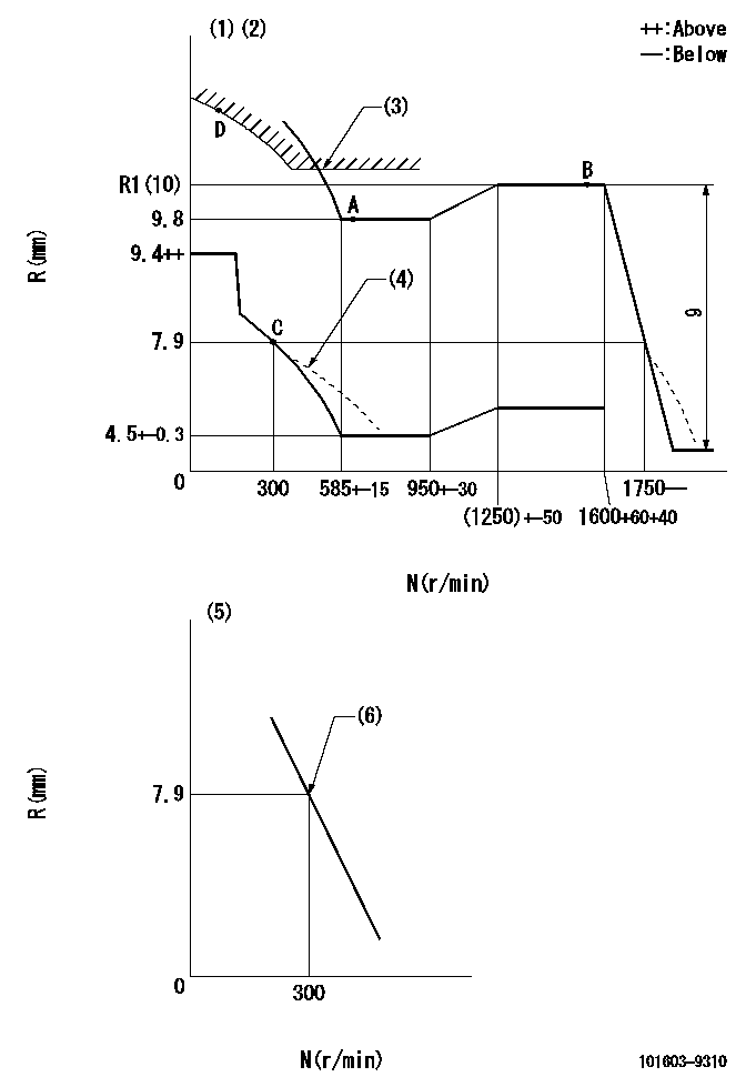
N:Pump speed
R:Rack position (mm)
(1)Lever ratio: RT
(2)Target shim dimension: TH
(3)Excess fuel setting for starting: SXL
(4)Damper spring setting: DL
(5)Variable speed specification: idling adjustment
(6)Main spring setting
----------
RT=1 TH=1.7mm SXL=R1+0.2mm DL=7-0.2mm
----------
----------
RT=1 TH=1.7mm SXL=R1+0.2mm DL=7-0.2mm
----------
Speed control lever angle
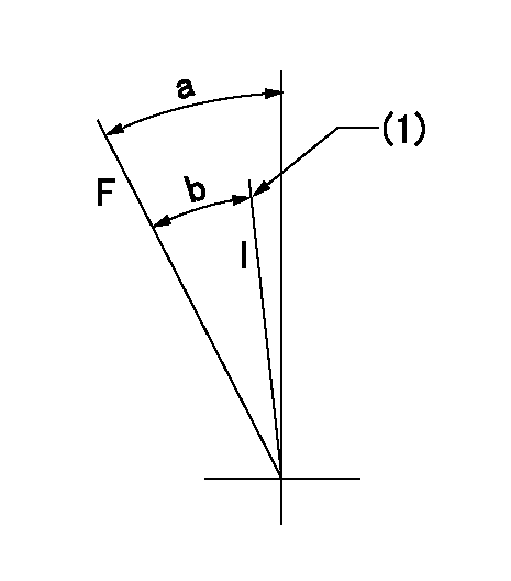
F:Full speed
I:Idle
(1)Stopper bolt setting
----------
----------
a=(24deg)+-5deg b=(20deg)+-5deg
----------
----------
a=(24deg)+-5deg b=(20deg)+-5deg
0000000901

F:Full load
I:Idle
(1)Stopper bolt setting
----------
----------
a=18deg+-5deg b=19.5deg+-3deg
----------
----------
a=18deg+-5deg b=19.5deg+-3deg
Stop lever angle

N:Pump normal
S:Stop the pump.
(1)Use the pin at R = aa
----------
aa=20mm
----------
a=40deg+-5deg b=71deg+-5deg
----------
aa=20mm
----------
a=40deg+-5deg b=71deg+-5deg
Timing setting

(1)Pump vertical direction
(2)Position of timer's threaded hole at No 1 cylinder's beginning of injection
(3)-
(4)-
----------
----------
a=(60deg)
----------
----------
a=(60deg)
Information:
Before any service work is done on the fuel system, the outer surface of the injection pump housing must be clean.
The fuel injection pump housing and governor has been removed from the engine for illustration purposes. 1. Remove flange (1) and the flange assembly from the cover.2. Remove cover (2) from the pump housing. 3. Remove the bypass valve (3) and springs from the pump housing.4. Install tooling (A) on the fuel injection pump and loosen the bushing from the pump housing. Do not loosen screws (4) that hold the levers to the shaft when the pumps are removed or installed. If the levers are moved, fuel pump calibration will be changed. 5. Remove the fuel injection pump (5) from the pump housing. The sleeve on the plunger will slide off the lever as the pump is removed.6. Do Steps 4 and 5 for the remainder of the pumps.Install Fuel Injection Pumps
1. Turn the camshaft until the lifter for the pump to be installed is at its lowest position.2. Install the fuel injection pump (1) in the bore of the pump housing. 3. The sleeve (2) will be engaged with the lever when the pump is installed correctly.
If the levers have been moved on the shaft, fuel pump calibration must be made. (See TESTING AND ADJUSTING).
4. Tighten the bushing with tooling (A) to a torque of 80 7 N m (60 5 lb.ft.).5. Do Steps 1 through 4 for the remainder of the pumps. 6. Install the bypass valve and spring (3) in the pump housing.7. Install the cover (5) on the pump housing. Be sure the spring (3) is in the bore in the cover. 8. Install the flange (4) and the flange assembly on the cover.Disassemble Fuel Injection Pumps
1. Remove bushing (1) and O-ring seal (7) from bonnet (2).2. Remove ring (3) from the bonnet and barrel (4). 3. Remove check valve assembly (9) and spring (8) from the bonnet.4. Remove spring (10) and retainer washer (5).
Keep the plunger and sleeve with their respective barrel for installation. Do not use plungers, sleeves and barrels with other plungers, sleeves and barrels.
5. Remove plunger (11) and sleeve (6).Assemble Fuel Injection Pumps
1. Install the sleeve (4), plunger (5), spring (2) and washer (3) on barrel (1).
Be sure the sleeve and plunger are installed in their original barrel and the large hole in the plunger is up. The sleeve must be installed with the thin flange up.
2. Install the check valve assembly and spring in the bonnet. Connect the barrel and bonnet with the ring. Install the seal and bushing on the bonnet. end by:a) install fuel injection pumps
Have questions with 101603-9310?
Group cross 101603-9310 ZEXEL
Nissan-Diesel
101603-9310
INJECTION-PUMP ASSEMBLY