Information injection-pump assembly
BOSCH
9 400 615 293
9400615293
ZEXEL
101603-9283
1016039283
DAEWOO
65111017239
65111017239
Rating:
Service parts 101603-9283 INJECTION-PUMP ASSEMBLY:
1.
_
7.
COUPLING PLATE
8.
_
9.
_
10.
NOZZLE AND HOLDER ASSY
11.
Nozzle and Holder
12.
Open Pre:MPa(Kqf/cm2)
13.
NOZZLE-HOLDER
14.
NOZZLE
15.
NOZZLE SET
Cross reference number
BOSCH
9 400 615 293
9400615293
ZEXEL
101603-9283
1016039283
DAEWOO
65111017239
65111017239
Zexel num
Bosch num
Firm num
Name
101603-9283
9 400 615 293
65111017239 DAEWOO
INJECTION-PUMP ASSEMBLY
D1146 * K
D1146 * K
Calibration Data:
Adjustment conditions
Test oil
1404 Test oil ISO4113 or {SAEJ967d}
1404 Test oil ISO4113 or {SAEJ967d}
Test oil temperature
degC
40
40
45
Nozzle and nozzle holder
105780-8140
Bosch type code
EF8511/9A
Nozzle
105780-0000
Bosch type code
DN12SD12T
Nozzle holder
105780-2080
Bosch type code
EF8511/9
Opening pressure
MPa
17.2
Opening pressure
kgf/cm2
175
Injection pipe
Outer diameter - inner diameter - length (mm) mm 6-2-600
Outer diameter - inner diameter - length (mm) mm 6-2-600
Overflow valve
131424-1520
Overflow valve opening pressure
kPa
157
123
191
Overflow valve opening pressure
kgf/cm2
1.6
1.25
1.95
Tester oil delivery pressure
kPa
157
157
157
Tester oil delivery pressure
kgf/cm2
1.6
1.6
1.6
Direction of rotation (viewed from drive side)
Right R
Right R
Injection timing adjustment
Direction of rotation (viewed from drive side)
Right R
Right R
Injection order
6-2-4-1-
5-3
Pre-stroke
mm
4.6
4.55
4.65
Beginning of injection position
Drive side NO.1
Drive side NO.1
Difference between angles 1
Cal 6-2 deg. 60 59.5 60.5
Cal 6-2 deg. 60 59.5 60.5
Difference between angles 2
Cal 6-4 deg. 120 119.5 120.5
Cal 6-4 deg. 120 119.5 120.5
Difference between angles 3
Cal 6-1 deg. 180 179.5 180.5
Cal 6-1 deg. 180 179.5 180.5
Difference between angles 4
Cal 6-5 deg. 240 239.5 240.5
Cal 6-5 deg. 240 239.5 240.5
Difference between angles 5
Cal 6-3 deg. 300 299.5 300.5
Cal 6-3 deg. 300 299.5 300.5
Injection quantity adjustment
Adjusting point
-
Rack position
11.4
Pump speed
r/min
700
700
700
Average injection quantity
mm3/st.
74.8
73.2
76.4
Max. variation between cylinders
%
0
-2
2
Basic
*
Fixing the rack
*
Standard for adjustment of the maximum variation between cylinders
*
Injection quantity adjustment_02
Adjusting point
H
Rack position
10.2+-0.
5
Pump speed
r/min
250
250
250
Average injection quantity
mm3/st.
17
15.5
18.5
Max. variation between cylinders
%
0
-15
15
Fixing the rack
*
Standard for adjustment of the maximum variation between cylinders
*
Injection quantity adjustment_03
Adjusting point
A
Rack position
R1(11.4)
Pump speed
r/min
700
700
700
Average injection quantity
mm3/st.
74.8
73.8
75.8
Basic
*
Fixing the lever
*
Injection quantity adjustment_04
Adjusting point
B
Rack position
R1+0.1
Pump speed
r/min
1250
1250
1250
Average injection quantity
mm3/st.
80.2
76.2
84.2
Fixing the lever
*
Injection quantity adjustment_05
Adjusting point
C
Rack position
R1-0.25
Pump speed
r/min
500
500
500
Average injection quantity
mm3/st.
58.4
54.4
62.4
Fixing the lever
*
Injection quantity adjustment_06
Adjusting point
I
Rack position
-
Pump speed
r/min
100
100
100
Average injection quantity
mm3/st.
115
115
130
Fixing the lever
*
Rack limit
*
Timer adjustment
Pump speed
r/min
950--
Advance angle
deg.
0
0
0
Remarks
Start
Start
Timer adjustment_02
Pump speed
r/min
900
Advance angle
deg.
0.5
Timer adjustment_03
Pump speed
r/min
1250
Advance angle
deg.
4
3.5
4.5
Remarks
Finish
Finish
Test data Ex:
Governor adjustment
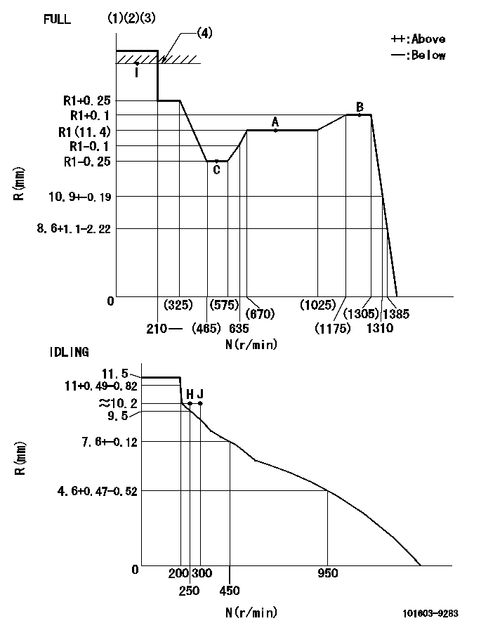
N:Pump speed
R:Rack position (mm)
(1)Torque cam stamping: T1
(2)Tolerance for racks not indicated: +-0.05mm.
(3)Microswitch adjustment unnecessary.
(4)RACK LIMIT
----------
T1=D58
----------
----------
T1=D58
----------
Speed control lever angle
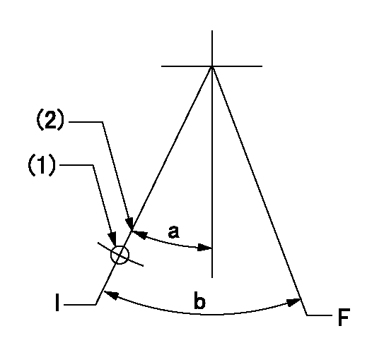
F:Full speed
I:Idle
(1)Use the hole at R = aa
(2)Stopper bolt set position 'H'
----------
aa=65mm
----------
a=24deg+-5deg b=37deg+-3deg
----------
aa=65mm
----------
a=24deg+-5deg b=37deg+-3deg
Stop lever angle

N:Pump normal
S:Stop the pump.
----------
----------
a=25deg+-5deg b=40deg+-5deg
----------
----------
a=25deg+-5deg b=40deg+-5deg
Timing setting

(1)Pump vertical direction
(2)Coupling's key groove position for the No. 6 cylinder's beginning of injection
(3)-
(4)-
----------
----------
a=(60deg)
----------
----------
a=(60deg)
Information:
start by:a) remove turbocharger 1. Make a mark on compressor housing (1), cartridge assembly (3) and the turbine housing (4) for correct installation. 2. Loosen clamp assembly (2). Remove compressor housing (1) and cartridge assembly (3) from the turbine housing.3. Remove bolts (6) and plates (5) that hold cartridge assembly in the compressor housing. Remove cartridge assembly (3). 4. Remove O-ring seal (7) from the cartridge assembly. 5. Put cartridge assembly (3) in position in tooling (A) and loosen nut on the compressor wheel with tooling (C).6. Remove nut (8) and the compressor wheel (9). 7. Remove shaft and wheel assembly (10) from the cartridge assembly. 8. Remove shroud (11) from the cartridge assembly. 9. Remove four bolts (12) and then remove backplate (13) from the cartridge assembly.10. Remove spacer (14) from the backplate. 11. Remove two seal rings (15) from the spacer. 12. Remove snap ring (16) from cartridge housing with tool (B). 13. Remove bearing (17) and rings from the cartridge housing.14. Remove snap ring (18) from cartridge housing with tool (B). 15. Turn the cartridge housing over and then remove screws (20), plate (21) and collar (19). 16. Remove bearing (22) from the cartridge housing. 17. Remove snap ring (23) from the cartridge housing with tool (B).Assemble Turbocharger
Make sure all of the oil passages in the turbocharger cartridge housing are clean and free of dirt and foreign material. Put clean engine oil on all parts of the cartridge assembly. 1. Install snap ring (1) in the cartridge housing with tool (A). Make sure the oil hole in plate (5) is open and clean to prevent a bearing failure.2. Install bearing (2), collars (3), plate (5) and screws (4). Tighten the screws to
Make sure all of the oil passages in the turbocharger cartridge housing are clean and free of dirt and foreign material. Put clean engine oil on all parts of the cartridge assembly. 1. Install snap ring (1) in the cartridge housing with tool (A). Make sure the oil hole in plate (5) is open and clean to prevent a bearing failure.2. Install bearing (2), collars (3), plate (5) and screws (4). Tighten the screws to
Have questions with 101603-9283?
Group cross 101603-9283 ZEXEL
Nissan-Diesel
Dpico
Yanmar
Daewoo
101603-9283
9 400 615 293
65111017239
INJECTION-PUMP ASSEMBLY
D1146
D1146