Information injection-pump assembly
ZEXEL
101603-9180
1016039180
Rating:
Service parts 101603-9180 INJECTION-PUMP ASSEMBLY:
1.
_
7.
COUPLING PLATE
8.
_
9.
_
11.
Nozzle and Holder
12.
Open Pre:MPa(Kqf/cm2)
21.6{220}

15.
NOZZLE SET
Cross reference number
ZEXEL
101603-9180
1016039180
Zexel num
Bosch num
Firm num
Name
Calibration Data:
Adjustment conditions
Test oil
1404 Test oil ISO4113 or {SAEJ967d}
1404 Test oil ISO4113 or {SAEJ967d}
Test oil temperature
degC
40
40
45
Nozzle and nozzle holder
105780-8140
Bosch type code
EF8511/9A
Nozzle
105780-0000
Bosch type code
DN12SD12T
Nozzle holder
105780-2080
Bosch type code
EF8511/9
Opening pressure
MPa
17.2
Opening pressure
kgf/cm2
175
Injection pipe
Outer diameter - inner diameter - length (mm) mm 6-2-600
Outer diameter - inner diameter - length (mm) mm 6-2-600
Overflow valve
131424-5120
Overflow valve opening pressure
kPa
255
221
289
Overflow valve opening pressure
kgf/cm2
2.6
2.25
2.95
Tester oil delivery pressure
kPa
157
157
157
Tester oil delivery pressure
kgf/cm2
1.6
1.6
1.6
Direction of rotation (viewed from drive side)
Right R
Right R
Injection timing adjustment
Direction of rotation (viewed from drive side)
Right R
Right R
Injection order
1-5-3-6-
2-4
Pre-stroke
mm
4.5
4.45
4.55
Beginning of injection position
Governor side NO.1
Governor side NO.1
Difference between angles 1
Cal 1-5 deg. 60 59.5 60.5
Cal 1-5 deg. 60 59.5 60.5
Difference between angles 2
Cal 1-3 deg. 120 119.5 120.5
Cal 1-3 deg. 120 119.5 120.5
Difference between angles 3
Cal 1-6 deg. 180 179.5 180.5
Cal 1-6 deg. 180 179.5 180.5
Difference between angles 4
Cyl.1-2 deg. 240 239.5 240.5
Cyl.1-2 deg. 240 239.5 240.5
Difference between angles 5
Cal 1-4 deg. 300 299.5 300.5
Cal 1-4 deg. 300 299.5 300.5
Injection quantity adjustment
Adjusting point
A
Rack position
9.9
Pump speed
r/min
950
950
950
Average injection quantity
mm3/st.
107.8
105.8
109.8
Max. variation between cylinders
%
0
-2.5
2.5
Basic
*
Fixing the lever
*
Injection quantity adjustment_02
Adjusting point
C
Rack position
8+-0.5
Pump speed
r/min
275
275
275
Average injection quantity
mm3/st.
17.2
15.2
19.2
Max. variation between cylinders
%
0
-15
15
Fixing the rack
*
Injection quantity adjustment_03
Adjusting point
D
Rack position
-
Pump speed
r/min
100
100
100
Average injection quantity
mm3/st.
145
125
165
Fixing the lever
*
Rack limit
*
Timer adjustment
Pump speed
r/min
950
Advance angle
deg.
0.5
Timer adjustment_02
Pump speed
r/min
-
Advance angle
deg.
4.5
4.5
4.5
Remarks
Measure the actual speed, stop
Measure the actual speed, stop
Test data Ex:
Governor adjustment
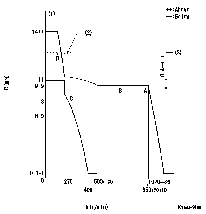
N:Pump speed
R:Rack position (mm)
(1)Target notch: K
(2)RACK LIMIT
(3)Rack difference between N = N1 and N = N2
----------
K=14 N1=950r/min N2=400r/min
----------
----------
K=14 N1=950r/min N2=400r/min
----------
Speed control lever angle
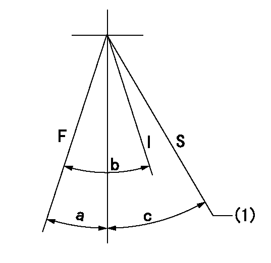
F:Full speed
I:Idle
S:Stop
(1)Rack position = aa
----------
aa=(0.5)mm
----------
a=3deg+-5deg b=29deg+-5deg c=35deg+-3deg
----------
aa=(0.5)mm
----------
a=3deg+-5deg b=29deg+-5deg c=35deg+-3deg
Stop lever angle
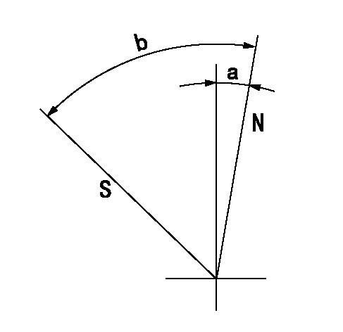
N:Pump normal
S:Stop the pump.
----------
----------
a=2.5deg+-5deg b=53deg+-5deg
----------
----------
a=2.5deg+-5deg b=53deg+-5deg
Timing setting

(1)Pump vertical direction
(2)Coupling's key groove position at No 1 cylinder's beginning of injection
(3)-
(4)-
----------
----------
a=(7deg)
----------
----------
a=(7deg)
Information:
2. Put transmission in direct gear and the differential in the highest speed ratio. Operate vehicle at maximum engine speed and increase chassis dynamometer load until a speed of 50 rpm less than rated speed is reached (continuity light should be on). Maintain this speed for one minute and record the engine speed and wheel horsepower. If horsepower is low and poor maintenance is suspected, remove air cleaner and check horsepower again to see if a plugged air cleaner could be the problem.3a. If the wheel horsepower is correct, find the set point (balance point) of the engine (speed at which the load stop pin just touches the torque spring or stop bar). At this point the continuity light should flicker (go off and on dimly).If the set point (balance point) is correct, then the low power complaint cannot be validated. No further test or repairs are necessary.If the set point (balance point) is low, see Procedure No. 4.3b. If the wheel horsepower is below the correct value, find the set point (balance point) of the engine (speed at which the load stop pin just touches the torque spring or stop bar). At this point the continuity light should flicker (go off and on dimly).If the set point (balance point) is correct, see Procedure No. 5.If the set point (balance point) is low, see Procedure No. 4.4. If the set point (balance point) is low, the high idle will have to be increased to raise the set point (balance point) to the correct rpm (the point at which the continuity light just comes on). If the set point (balance point) is still low and high idle has been adjusted to maximum, disengage clutch while maximum throttle position is maintained. Now observe high idle rpm and, if lower than previously adjusted, check frame-to-engine-mount. A damaged or loose engine mount may put the linkage in a bind and prevent maximum governor position at load conditions.5. If the set point (balance point) was correct and the wheel horsepower was low, install the 1U5470 Engine Pressure Group and do the wheel horsepower test again as shown in Procedure No 2.At full load rpm, measure the boost and the fuel pressure. See Fuel Setting and Related Information Fiche to find the correct boost pressure for a particular engine (since the engine is in vehicle, be sure to make reference to the General Notes in the Fuel Setting and Related Information Fiche to determine the correct boost pressure with air cleaner and muffler installed). If boost is low, check connections ahead of turbine side of turbocharger for exhaust leaks and connections after compressor side of turbocharger for inlet air leaks.6. Check the air inlet restriction and exhaust back pressure.Air flow through the air cleaner and piping must not have a vacuum restriction (negative pressure difference between atmospheric air and air that has gone through air cleaner) of more than 635 mm (25 in) of water. Back pressure from the exhaust (pressure difference measurement between