Information injection-pump assembly
ZEXEL
101603-9091
1016039091
Rating:
Cross reference number
ZEXEL
101603-9091
1016039091
Zexel num
Bosch num
Firm num
Name
Calibration Data:
Adjustment conditions
Test oil
1404 Test oil ISO4113 or {SAEJ967d}
1404 Test oil ISO4113 or {SAEJ967d}
Test oil temperature
degC
40
40
45
Nozzle and nozzle holder
105780-8140
Bosch type code
EF8511/9A
Nozzle
105780-0000
Bosch type code
DN12SD12T
Nozzle holder
105780-2080
Bosch type code
EF8511/9
Opening pressure
MPa
17.2
Opening pressure
kgf/cm2
175
Injection pipe
Outer diameter - inner diameter - length (mm) mm 6-2-600
Outer diameter - inner diameter - length (mm) mm 6-2-600
Overflow valve opening pressure
kPa
157
123
191
Overflow valve opening pressure
kgf/cm2
1.6
1.25
1.95
Tester oil delivery pressure
kPa
157
157
157
Tester oil delivery pressure
kgf/cm2
1.6
1.6
1.6
Direction of rotation (viewed from drive side)
Right R
Right R
Injection timing adjustment
Direction of rotation (viewed from drive side)
Right R
Right R
Injection order
1-4-2-6-
3-5
Pre-stroke
mm
3.4
3.35
3.45
Beginning of injection position
Drive side NO.1
Drive side NO.1
Difference between angles 1
Cal 1-4 deg. 60 59.5 60.5
Cal 1-4 deg. 60 59.5 60.5
Difference between angles 2
Cyl.1-2 deg. 120 119.5 120.5
Cyl.1-2 deg. 120 119.5 120.5
Difference between angles 3
Cal 1-6 deg. 180 179.5 180.5
Cal 1-6 deg. 180 179.5 180.5
Difference between angles 4
Cal 1-3 deg. 240 239.5 240.5
Cal 1-3 deg. 240 239.5 240.5
Difference between angles 5
Cal 1-5 deg. 300 299.5 300.5
Cal 1-5 deg. 300 299.5 300.5
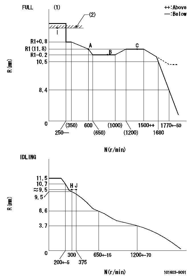
Injection quantity adjustment
Adjusting point
-
Rack position
11.8
Pump speed
r/min
600
600
600
Average injection quantity
mm3/st.
66.3
64.7
67.9
Max. variation between cylinders
%
0
-3.5
3.5
Basic
*
Fixing the rack
*
Standard for adjustment of the maximum variation between cylinders
*
Injection quantity adjustment_02
Adjusting point
H
Rack position
9.5+-0.5
Pump speed
r/min
300
300
300
Average injection quantity
mm3/st.
9.5
7.7
11.3
Max. variation between cylinders
%
0
-10
10
Fixing the rack
*
Standard for adjustment of the maximum variation between cylinders
*
Injection quantity adjustment_03
Adjusting point
A
Rack position
R1(11.8)
Pump speed
r/min
600
600
600
Average injection quantity
mm3/st.
66.3
65.3
67.3
Basic
*
Fixing the lever
*
Injection quantity adjustment_04
Adjusting point
B
Rack position
R1-0.2
Pump speed
r/min
900
900
900
Average injection quantity
mm3/st.
73
69.8
76.2
Fixing the lever
*
Injection quantity adjustment_05
Adjusting point
C
Rack position
R1(11.8)
Pump speed
r/min
1500
1500
1500
Average injection quantity
mm3/st.
83.9
79.9
87.9
Fixing the lever
*
Injection quantity adjustment_06
Adjusting point
I
Rack position
-
Pump speed
r/min
100
100
100
Average injection quantity
mm3/st.
84
84
94
Fixing the lever
*
Rack limit
*
Timer adjustment
Pump speed
r/min
1250--
Advance angle
deg.
0
0
0
Remarks
Start
Start
Timer adjustment_02
Pump speed
r/min
1200
Advance angle
deg.
0.5
Timer adjustment_03
Pump speed
r/min
1500
Advance angle
deg.
4
3.5
4.5
Remarks
Finish
Finish
Test data Ex:
Governor adjustment
N:Pump speed
R:Rack position (mm)
(1)Torque cam stamping: T1
(2)RACK LIMIT
----------
T1=C43
----------
----------
T1=C43
----------
Speed control lever angle

F:Full speed
I:Idle
(1)Stopper bolt set position 'H'
----------
----------
a=26.5deg+-5deg b=40deg+-3deg
----------
----------
a=26.5deg+-5deg b=40deg+-3deg
Stop lever angle

N:Pump normal
S:Stop the pump.
----------
----------
a=20deg+-5deg b=40deg+-5deg
----------
----------
a=20deg+-5deg b=40deg+-5deg
Timing setting

(1)Pump vertical direction
(2)Position of timer's threaded hole at No 1 cylinder's beginning of injection
(3)-
(4)-
----------
----------
a=(60deg)
----------
----------
a=(60deg)
Information:
Table 1
Part Number Container Size Volume of Finished Coolant Produced
351-9431 3.8 L (1 US gal) 50.5 L (13.3 US gal)
351-9432 20 L (5.3 US gal) 267 L (70.5 US gal)
351-9433 208 L (55 US gal) 2773 L (733 US gal)
366-2753 (1) 1000 L (264 US gal) 13333 L (3523 US gal)
(1) NACD and LACD onlyMixing Cat ELI
The recommended water for mixing with Cat ELI concentrate is distilled or deionized water. Water must meet requirements of ASTM 1193, "Type IV Reagent Water Specification". If distilled or deionized water is not available, water should meet the “Caterpillar Minimum Acceptable Water Requirements” provided in this Special Publication.To ensure a proper concentration, the preferred method is to mix Cat ELI concentrate with water. Then, add the mixed coolant to the engine cooling system. Add the proper amounts of water and Cat ELI into a clean container and mix thoroughly by manual stirring or mechanical agitation.If the preferred method cannot be performed, a Cat ELI mixture can be made by adding Cat ELI concentrate directly into engine cooling system. Add good quality water until the dilution level is approximately 7.5%. Adequate mixing is attained by operating the engine for at least 30 minutes.Appropriate mixing rates for available ELI container sizes are provided in Table 1.After the addition of water and proper mixing, the concentration of Cat ELI can be determined using the 360-0774 Digital Brix Refractometer.Changing to Cat ELI
For cooling systems previously running Cat ELC or an extended life coolant that meets Cat EC-1 requirements, drain the cooling system and flush with water. Then refill the cooling system with a mixture of 7.5% Cat ELI in water that meets the “Caterpillar Minimum Acceptable Water Requirements”.For cooling systems previously running a conventional heavy-duty coolant or a water/SCA mixture, follow the steps listed in this Special Publication, "Changing to Cat ELC". Then refill the cooling system with a mixture of 7.5% Cat ELI in water that meets the “Caterpillar Minimum Acceptable Water Requirements”.Cat ELI Maintenance
Maintenance of Cat ELI is similar to Cat ELC. A coolant sample should be submitted for S O S Level 2 Coolant Analysis after the first 500 hours of operation and then annually thereafter.Cat ELC Extender should be added at the midpoint of service life (typically 6,000 hours), or as recommended by S O S Coolant Analysis results.Analysis and interpretation of Cat ELI S O S results is similar to the analysis and interpretation of Cat ELC. There will be no glycol and glycol oxidation products, which do not apply to Cat ELI.The concentration of a sample of in-use Cat ELI taken from the cooling system can also be determined using the 360-0774 Digital Brix Refractometer.Note: Clean water is the only flushing agent that is required when Cat ELI is drained from a properly maintained cooling system.Mixing Cat ELI and Cat ELC
Since Cat ELI and Cat ELC are based on the same corrosion inhibitor technology, Cat ELI can be mixed with Cat