Information injection-pump assembly
BOSCH
9 400 615 288
9400615288
ZEXEL
101603-9063
1016039063
NISSAN-DIESEL
16700Z5706
16700z5706

Rating:
Service parts 101603-9063 INJECTION-PUMP ASSEMBLY:
1.
_
7.
COUPLING PLATE
8.
_
9.
_
11.
Nozzle and Holder
16600-Z5519
12.
Open Pre:MPa(Kqf/cm2)
19.6{200}
15.
NOZZLE SET
Cross reference number
BOSCH
9 400 615 288
9400615288
ZEXEL
101603-9063
1016039063
NISSAN-DIESEL
16700Z5706
16700z5706
Zexel num
Bosch num
Firm num
Name
9 400 615 288
16700Z5706 NISSAN-DIESEL
INJECTION-PUMP ASSEMBLY
FE6B * K 14BE PE6A PE
FE6B * K 14BE PE6A PE
Calibration Data:
Adjustment conditions
Test oil
1404 Test oil ISO4113 or {SAEJ967d}
1404 Test oil ISO4113 or {SAEJ967d}
Test oil temperature
degC
40
40
45
Nozzle and nozzle holder
105780-8140
Bosch type code
EF8511/9A
Nozzle
105780-0000
Bosch type code
DN12SD12T
Nozzle holder
105780-2080
Bosch type code
EF8511/9
Opening pressure
MPa
17.2
Opening pressure
kgf/cm2
175
Injection pipe
Outer diameter - inner diameter - length (mm) mm 6-2-600
Outer diameter - inner diameter - length (mm) mm 6-2-600
Overflow valve
131424-1520
Overflow valve opening pressure
kPa
157
123
191
Overflow valve opening pressure
kgf/cm2
1.6
1.25
1.95
Tester oil delivery pressure
kPa
157
157
157
Tester oil delivery pressure
kgf/cm2
1.6
1.6
1.6
Direction of rotation (viewed from drive side)
Right R
Right R
Injection timing adjustment
Direction of rotation (viewed from drive side)
Right R
Right R
Injection order
1-4-2-6-
3-5
Pre-stroke
mm
3.4
3.35
3.45
Beginning of injection position
Drive side NO.1
Drive side NO.1
Difference between angles 1
Cal 1-4 deg. 60 59.5 60.5
Cal 1-4 deg. 60 59.5 60.5
Difference between angles 2
Cyl.1-2 deg. 120 119.5 120.5
Cyl.1-2 deg. 120 119.5 120.5
Difference between angles 3
Cal 1-6 deg. 180 179.5 180.5
Cal 1-6 deg. 180 179.5 180.5
Difference between angles 4
Cal 1-3 deg. 240 239.5 240.5
Cal 1-3 deg. 240 239.5 240.5
Difference between angles 5
Cal 1-5 deg. 300 299.5 300.5
Cal 1-5 deg. 300 299.5 300.5
Injection quantity adjustment
Adjusting point
A
Rack position
9.8
Pump speed
r/min
600
600
600
Average injection quantity
mm3/st.
58.9
57.9
59.9
Max. variation between cylinders
%
0
-3.5
3.5
Basic
*
Fixing the lever
*
Injection quantity adjustment_02
Adjusting point
B
Rack position
R1(10)
Pump speed
r/min
1500
1500
1500
Average injection quantity
mm3/st.
80.6
79.6
81.6
Max. variation between cylinders
%
0
-5
5
Fixing the lever
*
Injection quantity adjustment_03
Adjusting point
C
Rack position
7.9+-0.5
Pump speed
r/min
300
300
300
Average injection quantity
mm3/st.
8.3
6.5
10.1
Max. variation between cylinders
%
0
-10
10
Fixing the rack
*
Injection quantity adjustment_04
Adjusting point
D
Rack position
-
Pump speed
r/min
100
100
100
Average injection quantity
mm3/st.
80
80
Fixing the lever
*
Remarks
After startup boost setting
After startup boost setting
Timer adjustment
Pump speed
r/min
850--
Advance angle
deg.
0
0
0
Remarks
Start
Start
Timer adjustment_02
Pump speed
r/min
800
Advance angle
deg.
0.5
Timer adjustment_03
Pump speed
r/min
1500
Advance angle
deg.
4
3.5
4.5
Remarks
Finish
Finish
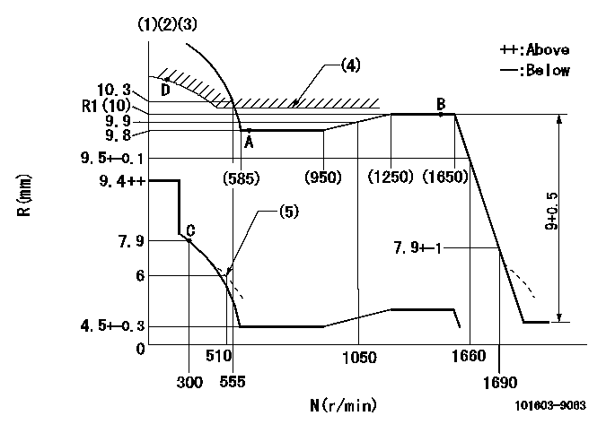
Test data Ex:
Governor adjustment

N:Pump speed
R:Rack position (mm)
(1)Lever ratio: RT
(2)Target shim dimension: TH
(3)Tolerance for racks not indicated: +-0.05mm.
(4)Excess fuel setting for starting: SXL (N = N1)
(5)Damper spring setting
----------
RT=1 TH=1.8mm SXL=R1+0.2mm N1=500r/min
----------
----------
RT=1 TH=1.8mm SXL=R1+0.2mm N1=500r/min
----------
0000000901

F:Full load
I:Idle
(1)Stopper bolt setting
----------
----------
a=18deg+-5deg b=19.5deg+-3deg
----------
----------
a=18deg+-5deg b=19.5deg+-3deg
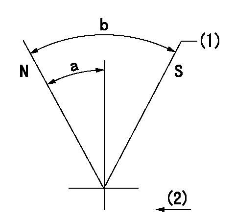
Stop lever angle

N:Pump normal
S:Stop the pump.
(1)Use the pin at R = aa
(2)Drive side
----------
aa=20mm
----------
a=40deg+-5deg b=71deg+-5deg
----------
aa=20mm
----------
a=40deg+-5deg b=71deg+-5deg
Timing setting

(1)Pump vertical direction
(2)Position of timer's threaded hole at No 1 cylinder's beginning of injection
(3)-
(4)-
----------
----------
a=(60deg)
----------
----------
a=(60deg)
Information:
3. Remove the connecting rod caps (1) from these pistons, and push the pistons upward until the rings clear the cylinder liner. 4. Remove the two pistons.5. Repeat Step 2 through 4 for the remaining pistons.Install Pistons
1. Thoroughly lubricate the crankshaft bearing journals and cylinder liners with clean SAE 30 engine oil.2. Lubricate the piston rings and connecting rod bearings with clean SAE 30 engine oil. 3. Using compressor (A), install the pistons with "V" mark on piston aligned with "V" mark on cylinder block. Guide the lower end of the rod over the crankshaft journal to prevent damage to the crankshaft.4. Lubricate the threads of cap retaining bolts with clean SAE 30 engine oil.5. Position the caps on the connecting rods, and install retaining nuts. Tighten nuts initially to 30 3 lb. ft. (4,1 0,4 mkg). Mark the nut and end of bolt, and tighten nut an additional 90° from mark.
When installing connecting rod cap, be sure that the number marked on side of cap is adjacent to and corresponds to the number marked on side of connecting rod.
6. Rotate the crankshaft until the next two bearing journals are at bottom dead center.7. Repeat Steps 2 through 5 for the remaining two pistons.concluding steps: a) install oil pumpb) install cylinder head assemblyDisassemble Pistons
preparatory step: a) remove pistons 1. Remove piston pin retaining rings (2).2. Remove piston pin (1) and remove piston from the connecting rod. 3. Remove the piston rings using ring expander (A).Assemble Pistons
1. Using ring expander (A), install the piston rings. The two compression rings are marked "UP - 1" and "UP - 2". The rings must be installed with these marks toward the top of the piston with "UP - 1" being the top ring. After all three rings have been installed on piston, stagger the ring caps 120° apart.2. Lubricate the piston pin with clean SAE 30 engine oil. 3. Position the piston on the connecting rod with the "V" mark (2) on the piston and number (1) on the connecting rod on the same side.4. Install the piston pin retaining rings. Make certain the retaining rings are seated in their grooves.concluding step: a) install pistons
