Information injection-pump assembly
ZEXEL
101603-9060
1016039060

Rating:
Cross reference number
ZEXEL
101603-9060
1016039060
Zexel num
Bosch num
Firm num
Name
Calibration Data:
Adjustment conditions
Test oil
1404 Test oil ISO4113 or {SAEJ967d}
1404 Test oil ISO4113 or {SAEJ967d}
Test oil temperature
degC
40
40
45
Nozzle and nozzle holder
105780-8140
Bosch type code
EF8511/9A
Nozzle
105780-0000
Bosch type code
DN12SD12T
Nozzle holder
105780-2080
Bosch type code
EF8511/9
Opening pressure
MPa
17.2
Opening pressure
kgf/cm2
175
Injection pipe
Outer diameter - inner diameter - length (mm) mm 6-2-600
Outer diameter - inner diameter - length (mm) mm 6-2-600
Overflow valve opening pressure
kPa
157
123
191
Overflow valve opening pressure
kgf/cm2
1.6
1.25
1.95
Tester oil delivery pressure
kPa
157
157
157
Tester oil delivery pressure
kgf/cm2
1.6
1.6
1.6
Direction of rotation (viewed from drive side)
Right R
Right R
Injection timing adjustment
Direction of rotation (viewed from drive side)
Right R
Right R
Injection order
1-4-2-6-
3-5
Pre-stroke
mm
3.4
3.35
3.45
Beginning of injection position
Drive side NO.1
Drive side NO.1
Difference between angles 1
Cal 1-4 deg. 60 59.5 60.5
Cal 1-4 deg. 60 59.5 60.5
Difference between angles 2
Cyl.1-2 deg. 120 119.5 120.5
Cyl.1-2 deg. 120 119.5 120.5
Difference between angles 3
Cal 1-6 deg. 180 179.5 180.5
Cal 1-6 deg. 180 179.5 180.5
Difference between angles 4
Cal 1-3 deg. 240 239.5 240.5
Cal 1-3 deg. 240 239.5 240.5
Difference between angles 5
Cal 1-5 deg. 300 299.5 300.5
Cal 1-5 deg. 300 299.5 300.5
Injection quantity adjustment
Adjusting point
A
Rack position
9.8
Pump speed
r/min
600
600
600
Average injection quantity
mm3/st.
58.9
57.9
59.9
Max. variation between cylinders
%
0
-3.5
3.5
Basic
*
Fixing the lever
*
Injection quantity adjustment_02
Adjusting point
B
Rack position
R1(10)
Pump speed
r/min
1500
1500
1500
Average injection quantity
mm3/st.
80.6
79.6
81.6
Max. variation between cylinders
%
0
-5
5
Fixing the lever
*
Injection quantity adjustment_03
Adjusting point
C
Rack position
7.9+-0.5
Pump speed
r/min
300
300
300
Average injection quantity
mm3/st.
8.3
6.5
10.1
Max. variation between cylinders
%
0
-10
10
Fixing the rack
*
Injection quantity adjustment_04
Adjusting point
D
Rack position
-
Pump speed
r/min
100
100
100
Average injection quantity
mm3/st.
80
80
Fixing the lever
*
Remarks
After startup boost setting
After startup boost setting
Timer adjustment
Pump speed
r/min
850--
Advance angle
deg.
0
0
0
Remarks
Start
Start
Timer adjustment_02
Pump speed
r/min
800
Advance angle
deg.
0.5
Timer adjustment_03
Pump speed
r/min
1500
Advance angle
deg.
4
3.5
4.5
Remarks
Finish
Finish
Test data Ex:
Governor adjustment
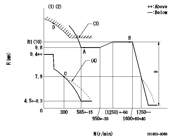
N:Pump speed
R:Rack position (mm)
(1)Lever ratio: RT
(2)Target shim dimension: TH
(3)Excess fuel setting for starting: SXL
(4)Damper spring setting: DL
----------
RT=1 TH=1.7mm SXL=R1+0.2mm DL=7-0.2mm
----------
----------
RT=1 TH=1.7mm SXL=R1+0.2mm DL=7-0.2mm
----------
0000000901

F:Full load
I:Idle
(1)Stopper bolt setting
----------
----------
a=18deg+-5deg b=19.5deg+-3deg
----------
----------
a=18deg+-5deg b=19.5deg+-3deg
Stop lever angle

N:Pump normal
S:Stop the pump.
(1)Use the pin at R = aa
----------
aa=20mm
----------
a=40deg+-5deg b=71deg+-5deg
----------
aa=20mm
----------
a=40deg+-5deg b=71deg+-5deg
Timing setting

(1)Pump vertical direction
(2)Position of timer's threaded hole at No 1 cylinder's beginning of injection
(3)-
(4)-
----------
----------
a=(60deg)
----------
----------
a=(60deg)
Information:
preparatory steps: a) remove timing gear coverb) remove fuel injection pump housing and governorc) remove fuel transfer pump 1. Disconnect the accessory drive oil supply line (1) and the fuel drain line (2). Remove the fuel priming pump.2. Remove the accessory drive shaft gear retaining nut, washer, and sleeve. 3. Using tool (A), remove the accessory drive gear. 4. Remove four retaining bolts (3), two locks and retainer (4).5. Remove the accessory drive housing.6. Remove the accessory drive shaft and bearing as a unit from the housing. 7. Using tool (B), remove bearing (5).Install Accessory Drive Shaft
1. Heat the accessory drive shaft bearing to 300°F (149°C) and install the bearing on the shaft. 2. Install the accessory drive shaft and bearing (1) in the housing.3. Install the accessory drive housing. 4. Install the retainer, locks and retaining bolts.5. Locate top center (TC) compression stroke for No. 1 piston. See LOCATING TOP CENTER COMPRESSION POSITION FOR No. 1 PISTON in TESTING AND ADJUSTING. 6. Rotate the accessory drive shaft until tool (A) can be installed. 7. Install the accessory drive shaft sleeve, drive gear, conical washer and nut. Install the conical washer on the drive shaft with the O.D. in contact with the gear. Tighten the retaining nut (2) to 100 10 lb. ft. (13,8 1,4 mkg).8. Connect the fuel drain line and the oil supply line. Install the fuel priming pump.concluding steps: a) install fuel transfer pumpb) install fuel injection pump housing and governorc) install timing gear cover
1. Heat the accessory drive shaft bearing to 300°F (149°C) and install the bearing on the shaft. 2. Install the accessory drive shaft and bearing (1) in the housing.3. Install the accessory drive housing. 4. Install the retainer, locks and retaining bolts.5. Locate top center (TC) compression stroke for No. 1 piston. See LOCATING TOP CENTER COMPRESSION POSITION FOR No. 1 PISTON in TESTING AND ADJUSTING. 6. Rotate the accessory drive shaft until tool (A) can be installed. 7. Install the accessory drive shaft sleeve, drive gear, conical washer and nut. Install the conical washer on the drive shaft with the O.D. in contact with the gear. Tighten the retaining nut (2) to 100 10 lb. ft. (13,8 1,4 mkg).8. Connect the fuel drain line and the oil supply line. Install the fuel priming pump.concluding steps: a) install fuel transfer pumpb) install fuel injection pump housing and governorc) install timing gear cover