Information injection-pump assembly
ZEXEL
101603-9040
1016039040
NISSAN-DIESEL
1671395100
1671395100
Rating:
Service parts 101603-9040 INJECTION-PUMP ASSEMBLY:
1.
_
7.
COUPLING PLATE
8.
_
9.
_
11.
Nozzle and Holder
1660095013
12.
Open Pre:MPa(Kqf/cm2)
19.6(200)

15.
NOZZLE SET
Include in #1:
101603-9040
as INJECTION-PUMP ASSEMBLY
Include in #2:
104749-5260
as _
Cross reference number
ZEXEL
101603-9040
1016039040
NISSAN-DIESEL
1671395100
1671395100
Zexel num
Bosch num
Firm num
Name
101603-9040
1671395100 NISSAN-DIESEL
INJECTION-PUMP ASSEMBLY
NE6 * K 14BE PE6A PE
NE6 * K 14BE PE6A PE
Calibration Data:
Adjustment conditions
Test oil
1404 Test oil ISO4113 or {SAEJ967d}
1404 Test oil ISO4113 or {SAEJ967d}
Test oil temperature
degC
40
40
45
Nozzle and nozzle holder
105780-8140
Bosch type code
EF8511/9A
Nozzle
105780-0000
Bosch type code
DN12SD12T
Nozzle holder
105780-2080
Bosch type code
EF8511/9
Opening pressure
MPa
17.2
Opening pressure
kgf/cm2
175
Injection pipe
Outer diameter - inner diameter - length (mm) mm 6-2-600
Outer diameter - inner diameter - length (mm) mm 6-2-600
Overflow valve opening pressure
kPa
157
123
191
Overflow valve opening pressure
kgf/cm2
1.6
1.25
1.95
Tester oil delivery pressure
kPa
157
157
157
Tester oil delivery pressure
kgf/cm2
1.6
1.6
1.6
Direction of rotation (viewed from drive side)
Right R
Right R
Injection timing adjustment
Direction of rotation (viewed from drive side)
Right R
Right R
Injection order
1-4-2-6-
3-5
Pre-stroke
mm
2.75
2.7
2.8
Beginning of injection position
Drive side NO.1
Drive side NO.1
Difference between angles 1
Cal 1-4 deg. 60 59.5 60.5
Cal 1-4 deg. 60 59.5 60.5
Difference between angles 2
Cyl.1-2 deg. 120 119.5 120.5
Cyl.1-2 deg. 120 119.5 120.5
Difference between angles 3
Cal 1-6 deg. 180 179.5 180.5
Cal 1-6 deg. 180 179.5 180.5
Difference between angles 4
Cal 1-3 deg. 240 239.5 240.5
Cal 1-3 deg. 240 239.5 240.5
Difference between angles 5
Cal 1-5 deg. 300 299.5 300.5
Cal 1-5 deg. 300 299.5 300.5
Injection quantity adjustment
Adjusting point
A
Rack position
9.7
Pump speed
r/min
700
700
700
Average injection quantity
mm3/st.
79.1
78.1
80.1
Max. variation between cylinders
%
0
-3.5
3.5
Basic
*
Fixing the lever
*
Injection quantity adjustment_02
Adjusting point
-
Rack position
7.5+-0.5
Pump speed
r/min
285
285
285
Average injection quantity
mm3/st.
13
11.2
14.8
Max. variation between cylinders
%
0
-10
10
Fixing the rack
*
Remarks
Adjust only variation between cylinders; adjust governor according to governor specifications.
Adjust only variation between cylinders; adjust governor according to governor specifications.
Timer adjustment
Pump speed
r/min
550--
Advance angle
deg.
0
0
0
Remarks
Start
Start
Timer adjustment_02
Pump speed
r/min
500
Advance angle
deg.
0.5
Timer adjustment_03
Pump speed
r/min
800
Advance angle
deg.
1.5
1
2
Timer adjustment_04
Pump speed
r/min
1200
Advance angle
deg.
4
3.5
4.5
Remarks
Finish
Finish
Test data Ex:
Governor adjustment
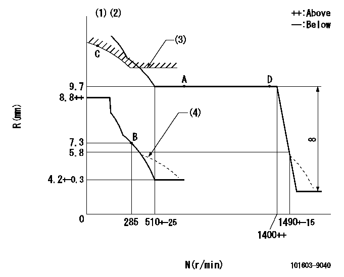
N:Pump speed
R:Rack position (mm)
(1)Lever ratio: RT
(2)Target shim dimension: TH
(3)Excess fuel setting for starting: SXL
(4)Damper spring setting: DL
----------
RT=1 TH=2.7mm SXL=11.8+0.2mm DL=5.7-0.2mm
----------
----------
RT=1 TH=2.7mm SXL=11.8+0.2mm DL=5.7-0.2mm
----------
Speed control lever angle

F:Full speed
----------
----------
a=(9.5deg)+-5deg
----------
----------
a=(9.5deg)+-5deg
0000000901

F:Full load
I:Idle
(1)Stopper bolt setting
----------
----------
a=18deg+-5deg b=21deg+-3deg
----------
----------
a=18deg+-5deg b=21deg+-3deg
Stop lever angle

N:Pump normal
S:Stop the pump.
(1)Use the pin at R = aa
----------
aa=20mm
----------
a=71deg+-5deg b=40deg+-5deg
----------
aa=20mm
----------
a=71deg+-5deg b=40deg+-5deg
Timing setting

(1)Pump vertical direction
(2)Position of coupling's key groove at No 1 cylinder's beginning of injection
(3)-
(4)-
----------
----------
a=(40deg)
----------
----------
a=(40deg)
Information:
preparatory step: a) remove oil pan1. Remove the suction screen mounting bolt.2. Remove the oil pump mounting bolts (1).3. Remove the oil pump-weight 40 lbs. (18,1 kg).Install Oil Pump
Prime the oil pump with SAE 30 engine oil before installation.
1. Position the oil pump on the engine, and install the pump mounting bolts and screen mounting bolt.concluding step: a) install oil panDisassemble Oil Pump
preparatory step: a) remove oil pump 1. Remove the oil pump idler gear (1). Using tool setup (A), remove the bearing from the gear.2. Remove the suction bell assembly (2) and relief valve oil tube (3). 3. Remove the relief valve (4) and spring (5).4. Using tool setup (B), pull the oil pump drive gear from the shaft. Remove the woodruff key. 5. Remove the oil pump housing cover (6).6. Remove the pump gears. 7. Using tool setup (C), remove the bearings from the pump housing and gear.8. Remove the bearing from the pump housing cover.Assemble Oil Pump
1. Using tool setup (A), install the bearing in the oil pump idler gear. Recess the bearing edge flush with the inner edge of the chamfer. 2. Using tool setup (B), install the bearings in the pump housing, pump gear and pump housing cover. Recess the bearing edge flush with the inner edge of the chamfer. 3. Lubricate the bearings, gears (1) and shaft with clean SAE 30 engine oil. Install the gears into the pump housing.4. Install the oil pump housing cover (2).5. Heat the oil pump drive gear to 350°F (177°C). Install the woodruff key and gear on the pump shaft.6. Install the relief valve and spring.7. Install the suction bell assembly, relief valve oil tube and install idler gear.concluding step: a) install oil pump
Have questions with 101603-9040?
Group cross 101603-9040 ZEXEL
Dpico
Nissan-Diesel
Nissan-Diesel
Nissan-Diesel
101603-9040
1671395100
INJECTION-PUMP ASSEMBLY
NE6
NE6