Information injection-pump assembly
ZEXEL
101603-9030
1016039030

Rating:
Cross reference number
ZEXEL
101603-9030
1016039030
Zexel num
Bosch num
Firm num
Name
Calibration Data:
Adjustment conditions
Test oil
1404 Test oil ISO4113 or {SAEJ967d}
1404 Test oil ISO4113 or {SAEJ967d}
Test oil temperature
degC
40
40
45
Nozzle and nozzle holder
105780-8140
Bosch type code
EF8511/9A
Nozzle
105780-0000
Bosch type code
DN12SD12T
Nozzle holder
105780-2080
Bosch type code
EF8511/9
Opening pressure
MPa
17.2
Opening pressure
kgf/cm2
175
Injection pipe
Outer diameter - inner diameter - length (mm) mm 6-2-600
Outer diameter - inner diameter - length (mm) mm 6-2-600
Overflow valve opening pressure
kPa
157
123
191
Overflow valve opening pressure
kgf/cm2
1.6
1.25
1.95
Tester oil delivery pressure
kPa
157
157
157
Tester oil delivery pressure
kgf/cm2
1.6
1.6
1.6
Direction of rotation (viewed from drive side)
Right R
Right R
Injection timing adjustment
Direction of rotation (viewed from drive side)
Right R
Right R
Injection order
1-4-2-6-
3-5
Pre-stroke
mm
3.4
3.35
3.45
Beginning of injection position
Drive side NO.1
Drive side NO.1
Difference between angles 1
Cal 1-4 deg. 60 59.5 60.5
Cal 1-4 deg. 60 59.5 60.5
Difference between angles 2
Cyl.1-2 deg. 120 119.5 120.5
Cyl.1-2 deg. 120 119.5 120.5
Difference between angles 3
Cal 1-6 deg. 180 179.5 180.5
Cal 1-6 deg. 180 179.5 180.5
Difference between angles 4
Cal 1-3 deg. 240 239.5 240.5
Cal 1-3 deg. 240 239.5 240.5
Difference between angles 5
Cal 1-5 deg. 300 299.5 300.5
Cal 1-5 deg. 300 299.5 300.5
Injection quantity adjustment
Adjusting point
-
Rack position
11.8
Pump speed
r/min
600
600
600
Average injection quantity
mm3/st.
66.3
64.7
67.9
Max. variation between cylinders
%
0
-3.5
3.5
Basic
*
Fixing the rack
*
Standard for adjustment of the maximum variation between cylinders
*
Injection quantity adjustment_02
Adjusting point
H
Rack position
9.5+-0.5
Pump speed
r/min
300
300
300
Average injection quantity
mm3/st.
9.5
7.7
11.3
Max. variation between cylinders
%
0
-10
10
Fixing the rack
*
Standard for adjustment of the maximum variation between cylinders
*
Injection quantity adjustment_03
Adjusting point
A
Rack position
R1(11.8)
Pump speed
r/min
600
600
600
Average injection quantity
mm3/st.
66.3
65.3
67.3
Basic
*
Fixing the lever
*
Injection quantity adjustment_04
Adjusting point
B
Rack position
R1-0.2
Pump speed
r/min
900
900
900
Average injection quantity
mm3/st.
73
69.8
76.2
Fixing the lever
*
Injection quantity adjustment_05
Adjusting point
C
Rack position
R1(11.8)
Pump speed
r/min
1500
1500
1500
Average injection quantity
mm3/st.
83.9
79.9
87.9
Fixing the lever
*
Injection quantity adjustment_06
Adjusting point
I
Rack position
-
Pump speed
r/min
100
100
100
Average injection quantity
mm3/st.
84
84
94
Fixing the lever
*
Rack limit
*
Timer adjustment
Pump speed
r/min
850--
Advance angle
deg.
0
0
0
Remarks
Start
Start
Timer adjustment_02
Pump speed
r/min
800
Advance angle
deg.
0.5
Timer adjustment_03
Pump speed
r/min
1500
Advance angle
deg.
4
3.5
4.5
Remarks
Finish
Finish
Test data Ex:
Governor adjustment
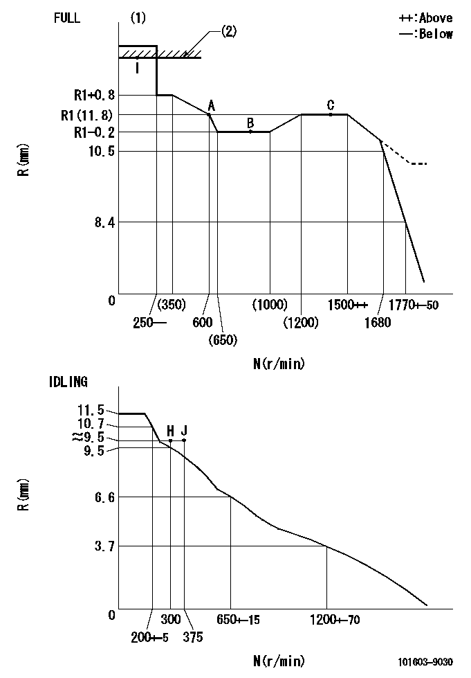
N:Pump speed
R:Rack position (mm)
(1)Torque cam stamping: T1
(2)RACK LIMIT
----------
T1=B55
----------
----------
T1=B55
----------
Speed control lever angle

F:Full speed
I:Idle
(1)Stopper bolt set position 'H'
----------
----------
a=26.5deg+-5deg b=40deg+-3deg
----------
----------
a=26.5deg+-5deg b=40deg+-3deg
Stop lever angle

N:Pump normal
S:Stop the pump.
----------
----------
a=20deg+-5deg b=40deg+-5deg
----------
----------
a=20deg+-5deg b=40deg+-5deg
Timing setting

(1)Pump vertical direction
(2)Position of timer's threaded hole at No 1 cylinder's beginning of injection
(3)-
(4)-
----------
----------
a=(60deg)
----------
----------
a=(60deg)
Information:
1. Disconnect the fuel priming pump fuel inlet line (1).2. Disconnect the fuel supply line.3. Remove the two mounting bolts (2) and remove the tachometer drive (4).4. Remove the two mounting bolts (3) and remove the fuel transfer pump.Install Fuel Transfer Pump
1. Position the fuel transfer pump on the engine and install the mounting bolts.2. Install the tachometer drive.3. Connect the fuel supply line.4. Connect the fuel priming pump fuel inlet line.5. Prime the fuel system and bleed off the air, with the fuel priming pump.Disassemble Fuel Transfer Pump
preparatory step: a) remove fuel transfer pump1. Remove the gear retaining nut (2), gear (3), and woodruff key.2. Remove the cage assembly (1).3. Remove the O-ring seals from the cage assembly. 4. Using tool (A), remove the bearing and lip-type seals from cage. 5. Remove the cover assembly (5).
Be careful not to damage mating surfaces of cover assembly and pump body.
6. Remove the seal from the cover assembly.7. Remove the gear (4), and gear and shaft assembly (6) from pump body. 8. Using tool (A), remove the bearing from pump body.Assemble Fuel Transfer Pump
1. Clean all parts thoroughly before assembling pump. 2. Using tool (A), install the bearing in pump body.3. Position the gear, and gear and shaft assembly in body. 4. Using tool (B), install the seal in the cover assembly.5. Apply a thin film of 8S6747 Liquid Gasket Material to face of body assembly.
Do not allow liquid gasket material to enter pump.
6. Install the cover assembly on pump body. After tightening cover assembly retaining bolts, the gear and shaft assembly must rotate freely. 7. Using tool (B), install the seals in the cage. Install the inner seal with lip of seal toward pump drive gear. Install the outer seal with lip toward pump body. 8. Using tool (A), install the bearing in the cage assembly.9. Install the O-ring seals on cage assembly.10. Lubricate the O-ring seals and lip-type seals with clean SAE 30 engine oil.11. Position the cage assembly on the gear and shaft assembly.12. Install the woodruff key, gear, and retaining nut. Tighten the retaining nut to 22 5 lb. ft. (3,0 0,7 mkg).concluding step: a) install fuel transfer pump