Information injection-pump assembly
BOSCH
9 400 611 700
9400611700
ZEXEL
101603-8993
1016038993
ISUZU
8943906047
8943906047
Rating:
Service parts 101603-8993 INJECTION-PUMP ASSEMBLY:
1.
_
7.
COUPLING PLATE
8.
_
9.
_
11.
Nozzle and Holder
8-94391-291-4
12.
Open Pre:MPa(Kqf/cm2)
16.2{165}/19.6{200}
14.
NOZZLE
Cross reference number
BOSCH
9 400 611 700
9400611700
ZEXEL
101603-8993
1016038993
ISUZU
8943906047
8943906047
Zexel num
Bosch num
Firm num
Name
9 400 611 700
8943906047 ISUZU
INJECTION-PUMP ASSEMBLY
6HL1-S * K 14BF PE6AD PE
6HL1-S * K 14BF PE6AD PE
Calibration Data:
Adjustment conditions
Test oil
1404 Test oil ISO4113 or {SAEJ967d}
1404 Test oil ISO4113 or {SAEJ967d}
Test oil temperature
degC
40
40
45
Nozzle and nozzle holder
105780-8260
Bosch type code
9 430 610 133
Nozzle
105780-0120
Bosch type code
1 688 901 990
Nozzle holder
105780-2190
Opening pressure
MPa
18
Opening pressure
kgf/cm2
184
Injection pipe
Outer diameter - inner diameter - length (mm) mm 6-2-600
Outer diameter - inner diameter - length (mm) mm 6-2-600
Overflow valve
131424-8620
Overflow valve opening pressure
kPa
206
172
240
Overflow valve opening pressure
kgf/cm2
2.1
1.75
2.45
Tester oil delivery pressure
kPa
255
255
255
Tester oil delivery pressure
kgf/cm2
2.6
2.6
2.6
Direction of rotation (viewed from drive side)
Left L
Left L
Injection timing adjustment
Direction of rotation (viewed from drive side)
Left L
Left L
Injection order
1-5-3-6-
2-4
Pre-stroke
mm
3.8
3.75
3.85
Rack position
Point A R=A
Point A R=A
Beginning of injection position
Governor side NO.1
Governor side NO.1
Difference between angles 1
Cal 1-5 deg. 60 59.5 60.5
Cal 1-5 deg. 60 59.5 60.5
Difference between angles 2
Cal 1-3 deg. 120 119.5 120.5
Cal 1-3 deg. 120 119.5 120.5
Difference between angles 3
Cal 1-6 deg. 180 179.5 180.5
Cal 1-6 deg. 180 179.5 180.5
Difference between angles 4
Cyl.1-2 deg. 240 239.5 240.5
Cyl.1-2 deg. 240 239.5 240.5
Difference between angles 5
Cal 1-4 deg. 300 299.5 300.5
Cal 1-4 deg. 300 299.5 300.5
Injection quantity adjustment
Adjusting point
-
Rack position
14.5
Pump speed
r/min
850
850
850
Average injection quantity
mm3/st.
133.5
131.9
135.1
Max. variation between cylinders
%
0
-2.5
2.5
Basic
*
Fixing the rack
*
Standard for adjustment of the maximum variation between cylinders
*
Injection quantity adjustment_02
Adjusting point
Z
Rack position
9.5+-0.5
Pump speed
r/min
300
300
300
Average injection quantity
mm3/st.
15.5
14.2
16.8
Max. variation between cylinders
%
0
-14
14
Fixing the rack
*
Standard for adjustment of the maximum variation between cylinders
*
Injection quantity adjustment_03
Adjusting point
A
Rack position
R1(14.5)
Pump speed
r/min
850
850
850
Average injection quantity
mm3/st.
133.5
132.5
134.5
Basic
*
Fixing the lever
*
Injection quantity adjustment_04
Adjusting point
B
Rack position
(R1+1.1)
+0.05-0.
15
Pump speed
r/min
1450
1450
1450
Average injection quantity
mm3/st.
133.5
130.3
136.7
Fixing the lever
*
Test data Ex:
Governor adjustment
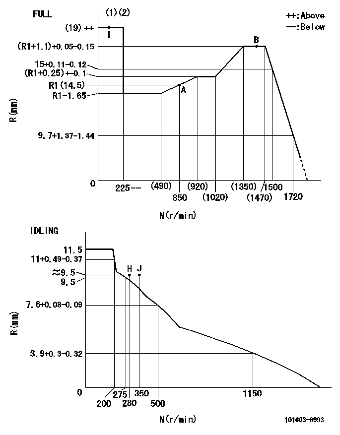
N:Pump speed
R:Rack position (mm)
(1)Torque cam stamping: T1
(2)Tolerance for racks not indicated: +-0.05mm.
----------
T1=P01
----------
----------
T1=P01
----------
Timer adjustment
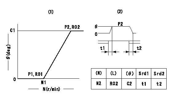
(1)Adjusting range
(2)Step response time
(N): Speed of the pump
(L): Load
(theta) Advance angle
(Srd1) Step response time 1
(Srd2) Step response time 2
1. Adjusting conditions for the variable timer
(1)Adjust the clearance between the pickup and the protrusion to L.
----------
L=1.5+-0.2mm N2=800r/min C2=(8deg) t1=2--sec. t2=2--sec.
----------
N1=1300++r/min P1=0kPa(0kgf/cm2) P2=392kPa(4kgf/cm2) C1=8+-0.3deg R01=0/4load R02=4/4load
----------
L=1.5+-0.2mm N2=800r/min C2=(8deg) t1=2--sec. t2=2--sec.
----------
N1=1300++r/min P1=0kPa(0kgf/cm2) P2=392kPa(4kgf/cm2) C1=8+-0.3deg R01=0/4load R02=4/4load
Speed control lever angle
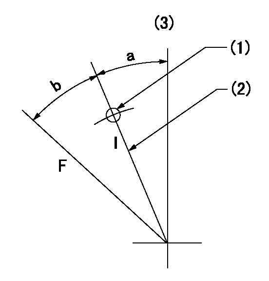
F:Full speed
I:Idle
(1)Use the pin at R = aa
(2)Stopper bolt set position 'H'
(3)Viewed from feed pump side.
----------
aa=35mm
----------
a=10deg+-5deg b=41deg+-3deg
----------
aa=35mm
----------
a=10deg+-5deg b=41deg+-3deg
Stop lever angle
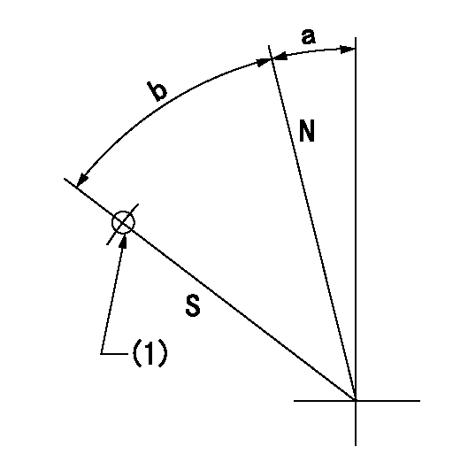
N:Pump normal
S:Stop the pump.
(1)Use the pin at R = aa
----------
aa=45mm
----------
a=12.5deg+-5deg b=40deg+-5deg
----------
aa=45mm
----------
a=12.5deg+-5deg b=40deg+-5deg
0000001501 RACK SENSOR
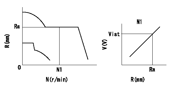
Rack sensor adjustment
1. Flange type rack sensor (rack sensor adjustment -5*20)
(1)These types of rack sensors do not need adjustment. Confirm the performance with the following procedures.
(2)Mount the rack sensor main body to the pump main body.
(3)Fix the pump lever at full.
(4)At supply voltage V1, pump speed N1 and rack position Ra, confirm that the amp's output voltage is Vist.
(5)Move the pump lever two or three times.
(6)Set again to full.
(7)Confirm that the amplifier output voltage is Vist.
(8)Fix the caution plate to the upper part of the rack sensor.
(For those without the caution plate instructions, make sure the nameplate of the rack sensor carries the "Don't hold here" caution.)
(9)Apply red paint to the rack sensor mounting bolts (2 places).
----------
V1=5+-0.01V N1=850r/min Ra=R1(14.5)mm Vist=3.74+-0.28V
----------
----------
V1=5+-0.01V N1=850r/min Ra=R1(14.5)mm Vist=3.74+-0.28V
----------
Timing setting
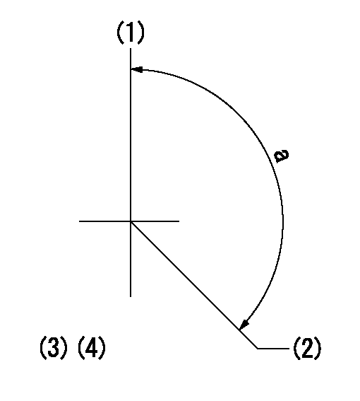
(1)Pump vertical direction
(2)Positions of coupling's threaded installation holes at No 1 cylinder's beginning of injection
(3)B.T.D.C.: aa
(4)-
----------
aa=6deg
----------
a=(160deg)
----------
aa=6deg
----------
a=(160deg)
Information:
Camshaft
When reconditioning an engine, check the diameter of the camshaft bearing journals and the camshaft lobe height.Camshaft bearing journals have a diameter of 2.5000 .0005 in. (63.500 0.013) and the minimum diameter worn is 2.4970 in. (63.424 mm).To measure height (B) of camshaft lobes, use the following procedures: 1. Measure base circle (C) of one exhaust and one intake lobe. Make a record of each dimension.2. Add lobe lift dimension (A) to each base circle measurement. The lobe lift dimension (A) is .3071 in. (7.800 mm) for the exhaust lobe and .3077 in. (7.816 mm) for the intake lobe.3. The minimum height of lobe (B) is .025 in. (0.64 mm) less than the dimension found in Step 2.Example of finding the height of a lobe:Base circle (C) ... 1.8200 in.(46.228 mm)Add lobe lift (A) ... .3077 in.(7.816 mm)Lobe height (B) ... 2.1277 in.(54.044 mm)Maximum wear of lobe ... .025 in.(0.64 mm)Minimum height of lobe ... 2.1027 in.(53.409 mm)
CAMSHAFT LOBE
A. Lobe lift. B. Lobe height. C. Base circle.With camshaft installed in the cylinder block, check end play. End play with new components should be .007 .003 in. (0.18 0.08 mm). The maximum permissible end play is .020 in. (0.51 mm).Camshaft Followers
Use an 8S2293 Magnet to remove the cam followers.
REMOVING CAM FOLLOWERSCam followers establish a wear pattern with the camshaft lobes. Identify and reinstall the followers in the same location from which they were removed. Dishing or circular wear pattern is allowed on the cam follower face, providing the wear face keeps a polished appearance. Replace the follower if the wear face is rough or shows signs of scuffing. A new follower can be used with an old camshaft, providing the lobe is in good condition. Put engine oil on the cam followers and the camshaft lobes before installing the cam followers. Use new cam followers with a new camshaft.Camshaft Gears
1100 and 3100 Engines With Fuel Pump Camshaft Mounted Timing Advance
1. Use a 1P2320 Puller to remove the camshaft small outer gear.
PULLING SMALL GEAR (Typical Example)2. Remove the spacer immediately behind the gear.3. Use a 1P2321 Puller to remove the camshaft large inner gear.
PULLING LARGE GEAR (Typical Example)4. To install, heat both gears to a maximum temperature of 600° F. (315° C).5. Align keyway of large gear with key in camshaft. Install large inner gear on camshaft with timing mark on gear aligned with timing mark on crankshaft gear.6. Install the spacer and small outer gear.
Do not drive gears onto camshaft. Serious damage can result to camshaft or camshaft thrust pin.
Engines With Engine Camshaft Mounted Timing Advance
1. Remove screw (1) and washer (2) from end of camshaft.
REMOVING TIMING ADVANCE RETAINING SCREW
1. Screw. 2. Washer.2. Remove timing advance unit from the camshaft.3. Install puller (A), with spacer (C) over the shaft in the camshaft and spacer (B) on spacer (C) as shown and remove the gear from the camshaft.
REMOVING GEAR (Typical Example)
A. 1P2321 Puller. B. 8S5579 Spacer. C. 9S9155 Spacer.To install the gear use the following procedure:1.