Information injection-pump assembly
BOSCH
9 400 615 284
9400615284
ZEXEL
101603-8931
1016038931
ISUZU
8943911701
8943911701
Rating:
Service parts 101603-8931 INJECTION-PUMP ASSEMBLY:
1.
_
7.
COUPLING PLATE
8.
_
9.
_
11.
Nozzle and Holder
8-94395-923-2
12.
Open Pre:MPa(Kqf/cm2)
22.1{225}
15.
NOZZLE SET
Cross reference number
BOSCH
9 400 615 284
9400615284
ZEXEL
101603-8931
1016038931
ISUZU
8943911701
8943911701
Zexel num
Bosch num
Firm num
Name
101603-8931
9 400 615 284
8943911701 ISUZU
INJECTION-PUMP ASSEMBLY
6HE1-TC K 14BF INJECTION PUMP ASSY PE6AD PE
6HE1-TC K 14BF INJECTION PUMP ASSY PE6AD PE
Calibration Data:
Adjustment conditions
Test oil
1404 Test oil ISO4113 or {SAEJ967d}
1404 Test oil ISO4113 or {SAEJ967d}
Test oil temperature
degC
40
40
45
Nozzle and nozzle holder
105780-8140
Bosch type code
EF8511/9A
Nozzle
105780-0000
Bosch type code
DN12SD12T
Nozzle holder
105780-2080
Bosch type code
EF8511/9
Opening pressure
MPa
17.2
Opening pressure
kgf/cm2
175
Injection pipe
Outer diameter - inner diameter - length (mm) mm 6-2-600
Outer diameter - inner diameter - length (mm) mm 6-2-600
Overflow valve
132424-0620
Overflow valve opening pressure
kPa
157
123
191
Overflow valve opening pressure
kgf/cm2
1.6
1.25
1.95
Tester oil delivery pressure
kPa
157
157
157
Tester oil delivery pressure
kgf/cm2
1.6
1.6
1.6
Direction of rotation (viewed from drive side)
Left L
Left L
Injection timing adjustment
Direction of rotation (viewed from drive side)
Left L
Left L
Injection order
1-5-3-6-
2-4
Pre-stroke
mm
3.5
3.45
3.55
Rack position
Point A R=A
Point A R=A
Beginning of injection position
Governor side NO.1
Governor side NO.1
Difference between angles 1
Cal 1-5 deg. 60 59.5 60.5
Cal 1-5 deg. 60 59.5 60.5
Difference between angles 2
Cal 1-3 deg. 120 119.5 120.5
Cal 1-3 deg. 120 119.5 120.5
Difference between angles 3
Cal 1-6 deg. 180 179.5 180.5
Cal 1-6 deg. 180 179.5 180.5
Difference between angles 4
Cyl.1-2 deg. 240 239.5 240.5
Cyl.1-2 deg. 240 239.5 240.5
Difference between angles 5
Cal 1-4 deg. 300 299.5 300.5
Cal 1-4 deg. 300 299.5 300.5
Injection quantity adjustment
Adjusting point
-
Rack position
12.2
Pump speed
r/min
850
850
850
Average injection quantity
mm3/st.
98
96.4
99.6
Max. variation between cylinders
%
0
-2.5
2.5
Basic
*
Fixing the rack
*
Standard for adjustment of the maximum variation between cylinders
*
Injection quantity adjustment_02
Adjusting point
H
Rack position
9.3+-0.5
Pump speed
r/min
265
265
265
Average injection quantity
mm3/st.
10.5
9.2
11.8
Max. variation between cylinders
%
0
-14
14
Fixing the rack
*
Standard for adjustment of the maximum variation between cylinders
*
Injection quantity adjustment_03
Adjusting point
A
Rack position
R1(12.2)
Pump speed
r/min
850
850
850
Average injection quantity
mm3/st.
98
97
99
Basic
*
Fixing the lever
*
Boost pressure
kPa
70.6
70.6
Boost pressure
mmHg
530
530
Injection quantity adjustment_04
Adjusting point
B
Rack position
(R1-0.2)
Pump speed
r/min
1350
1350
1350
Average injection quantity
mm3/st.
101
97.8
104.2
Fixing the lever
*
Boost pressure
kPa
70.6
70.6
Boost pressure
mmHg
530
530
Injection quantity adjustment_05
Adjusting point
C
Rack position
(R1-1.85
)
Pump speed
r/min
850
850
850
Average injection quantity
mm3/st.
57.5
54.3
60.7
Fixing the lever
*
Boost pressure
kPa
0
0
0
Boost pressure
mmHg
0
0
0
Injection quantity adjustment_06
Adjusting point
I
Rack position
-
Pump speed
r/min
150
150
150
Average injection quantity
mm3/st.
105
105
137
Fixing the lever
*
Boost pressure
kPa
0
0
0
Boost pressure
mmHg
0
0
0
Boost compensator adjustment
Pump speed
r/min
1050
1050
1050
Rack position
R2-1.85
Boost pressure
kPa
9.3
8
10.6
Boost pressure
mmHg
70
60
80
Boost compensator adjustment_02
Pump speed
r/min
1050
1050
1050
Rack position
R2[R1-0.
05]
Boost pressure
kPa
57.3
57.3
57.3
Boost pressure
mmHg
430
430
430
Timer adjustment
Pump speed
r/min
1150--
Advance angle
deg.
0
0
0
Remarks
Start
Start
Timer adjustment_02
Pump speed
r/min
1100
Advance angle
deg.
0.5
Timer adjustment_03
Pump speed
r/min
1400
Advance angle
deg.
2
1.5
2.5
Remarks
Finish
Finish
Test data Ex:
Governor adjustment
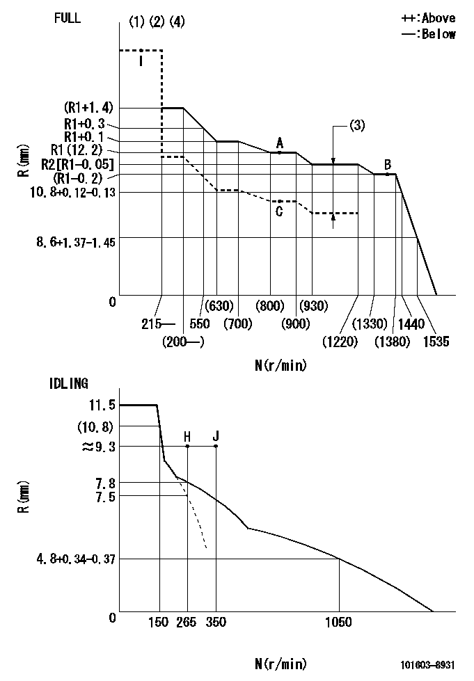
N:Pump speed
R:Rack position (mm)
(1)Torque cam stamping: T1
(2)Tolerance for racks not indicated: +-0.05mm.
(3)Boost compensator stroke: BCL
(4)Adjust so that the boost compensator pushrod protrusion R = Ra at 0 boost.
----------
T1=L05 BCL=1.85+-0.1mm Ra=12+-0.5mm
----------
----------
T1=L05 BCL=1.85+-0.1mm Ra=12+-0.5mm
----------
Speed control lever angle
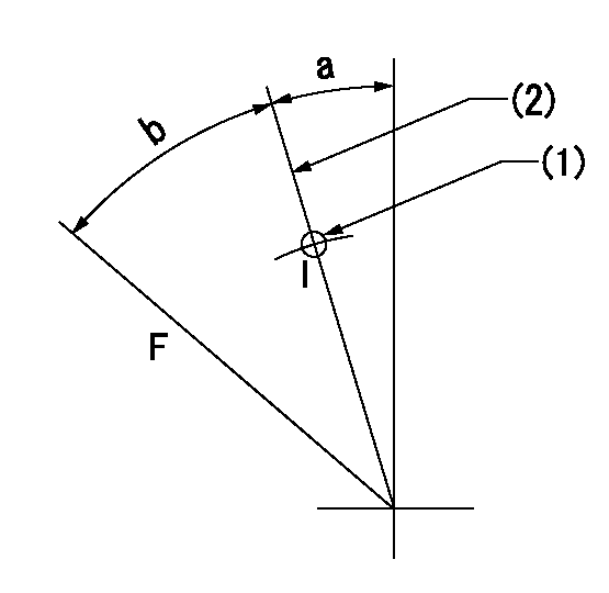
F:Full speed
I:Idle
(1)Use the pin at R = aa
(2)Stopper bolt setting
----------
aa=35mm
----------
a=17deg+-5deg b=28deg+-3deg
----------
aa=35mm
----------
a=17deg+-5deg b=28deg+-3deg
Stop lever angle
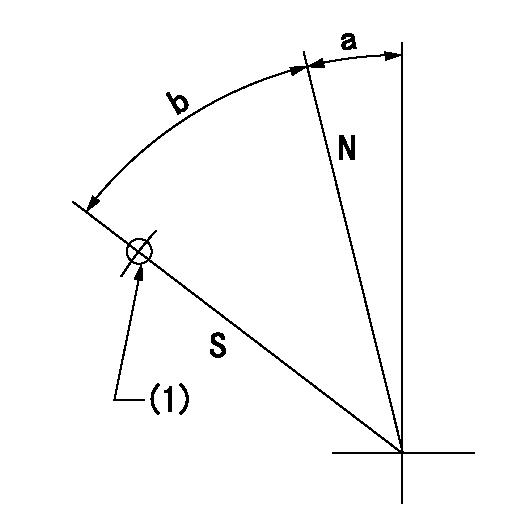
N:Pump normal
S:Stop the pump.
(1)Use the pin at R = aa
----------
aa=45mm
----------
a=12.5deg+-5deg b=40deg+-5deg
----------
aa=45mm
----------
a=12.5deg+-5deg b=40deg+-5deg
Timing setting
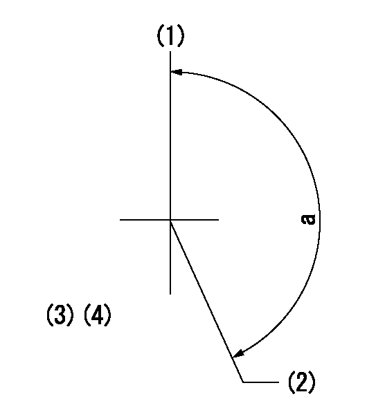
(1)Pump vertical direction
(2)Position of timer's threaded hole at No 1 cylinder's beginning of injection
(3)B.T.D.C.: aa
(4)-
----------
aa=13deg
----------
a=(150deg)
----------
aa=13deg
----------
a=(150deg)
Information:
TIMING MARKS2. Remove the plug from the timing pin hole in fuel injection pump housing and install timing pin (1).
TIMING PIN INSTALLED
1. FT887 Timing Pin (Fabricated Tool).3. Remove bolts (2) and tachometer drive assembly (3) from the fuel injection pump camshaft.
PUMP DRIVE GEAR
2. Bolts (three). 3. Tachometer drive assembly. 4. Drive gear.4. Remove the drive gear (4) from the fuel injection pump camshaft.
TIMING ADVANCE
5. Retaining screw. 6. Washer. 7. Automatic timing advance.5. Remove retaining screw (5), washer (6), and automatic timing advance (7) from the engine camshaft.6. Install puller (8), with spacer (10) over the shaft in the camshaft and spacer (9) on spacer (10) as shown and remove the gear from the camshaft.
REMOVING GEAR (Typical Example)
8. 1P2321 Puller. 9. 8S5579 Spacer. 10. 9S9155 Spacer.Install Camshaft Gear
1. Heat the gear to a temperature of approximately 400° F (204° C) before installing on the camshaft.
Do not head the gear with a torch. Do not heat the gear to a temperature of more than 600° F (315° C). Heating the gear with a torch or to a temperature of more than 600° F (315° C) may cause the two drive dowels for the automatic timing advance to loosen and come out of the gear.
TIMING MARKS2. Align slot in gear hub with the pin in the camshaft. Install the gear on the camshaft with timing mark on gear aligned with timing mark on crankshaft gear. Be sure the gear is completely seated against the shoulder of the camshaft.
Do not drive the gear on the camshaft. Serious damage can result to camshaft or camshaft thrust pin.
3. Align holes in weights with dowels in gear and install the automatic timing advance.4. Align pin (11) in washer (6) with hole (12) in camshaft and install washer (6).
INSTALLING WASHER
6. Washer. 11. Pin. 12. Hole.5. Install retaining screw (5) and tighten to 108 36 lb. in. (124.5 41.5 cm.kg). Stake screw (5) in two places.
Stake retaining screw (5) carefully. Heavy blows on washer or retaining screw can force the shaft extension too far into the camshaft and eliminate all end clearance.
STAKING SCREW (Typical Example)
5. Retaining screw.6. After retaining screw (5) is staked, the gear and weight assembly requires .003 to .027 in. (0.08 to 0.69 mm) end clearance to prevent binding against the washer, camshaft end, or camshaft gear.7. Put timing plate (14) on the engine and thread bolt (13) into the timing gear.
TIMING PLATE INSTALLED
13. Bolt. 14. 5P950 Timing Plate.8. Install drive gear (4) on the fuel injection pump camshaft with the holes in the position shown and the part number facing out. To be able to advance the timing adjustment without removing the front cover, position gear (4) in the direction of the arrow so the bolt holes in the fuel injection pump camshaft are off center as shown. The bolts must thread freely into the holes in the fuel injection pump camshaft.
GEAR INSTALLED
4. Drive gear.9. Install tachometer drive assembly (3) and tighten finger tight.10. Install bolts (2) and tighten the bolts
Have questions with 101603-8931?
Group cross 101603-8931 ZEXEL
Isuzu
101603-8931
9 400 615 284
8943911701
INJECTION-PUMP ASSEMBLY
6HE1-TC
6HE1-TC
